Components & Cladding for High Rise Buildings
Overview
In high-rise building design (height > 60 ft), determining the wind pressure on windows, louvers, panels, and other components and cladding (C&C) elements involves considering for both two positive and negative (suction) pressures. Since these pressures vary significantly with elevation, correctly applying ASCE 7-22 Chapter 30, Part 2 is essential for a code-compliant and structurally sound design.
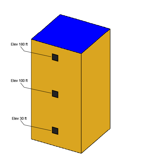
To help illustrate this point, this article will provide an example and walk through the steps of this process on how to determine components and cladding wind pressures at different building stories for high-rise buildings.
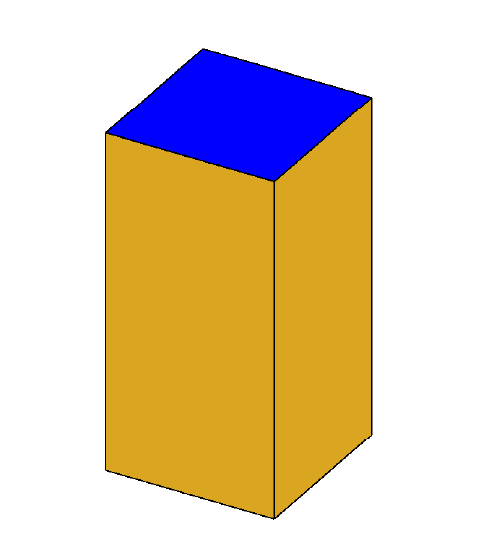
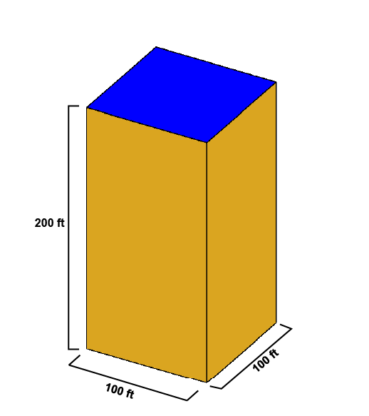
Our example will use a flat roof, enclosed building with a roof height of 200 ft and a width/length of 100 ft.
We will investigate the C&C wind pressure on 50 ft2 windows (5 ft wide, 10 ft tall) at three different elevations: 30 ft (low level), 100 ft (mid-height), and 180 ft (near roof).
Step 1: Confirm Applicability of Chapter 30, Part 2
Chapter 30 of ASCE 7-22 governs C&C wind pressures and is divided into five parts:
- Part 1 – Low-rise buildings (h ≤ 60 ft)
- Part 2 – Buildings with mean roof height h > 60 ft
- Part 3 – Open buildings of all heights
- Part 4 – Building appurtenances (roof overhangs, parapets, and rooftop equipment)
- Part 5 – Non-building structures (circular bins, silos, tanks, rooftop solar panels, and roof pavers)
For high-rise buildings, like our example, Part 2 applies. This section provides external pressure coefficients (GCp) using different figures that apply to applicable building characteristics, such as walls and roof types. The coefficients are then applied to other pressures and coefficients to calculate varying design wind pressures.
Step 2: Determine Design Parameters
- Risk category
- We will assume risk category III
- Basic wind speed, V, for applicable risk category
- We will assume V = 120 mph
- Wind directionality factor, Kd (Table 26.6-1)
- Components and cladding for buildings, Kd = 0.85
- Exposure category (Section 26.7)
- For an urban area, exposure category B is typical
- Thus, α = 7.5 and zg = 3,280 ft (Table 26.11-1)
- Topographic factor, Kzt (Section 26.8)
- We will assume Kzt = 1.0
- Ground elevation factor, Ke (Section 26.9)
- We will assume Ke = 1.0
- Enclosure classification (Defined in section 26.2)
- We will use an enclosed classification
- Internal pressure coefficient GCpi (Table 26.13-1)
For enclosed buildings, GCpi is +/- 0.18
Step 3: Determine elevation specific parameters
- Velocity pressure coefficient, Kz and Kh (Table 26.10-1)
- We will be utilizing the formula from the table
- For 15 ft <= z <= zg, Kz = 2.41*(z/zg)(2/α)
- Velocity pressure, qz and qh (Equation 26.10-1)
- qz = 0.00256*Kz*Kzt*Ke*V2
- We will be utilizing the formula from the table
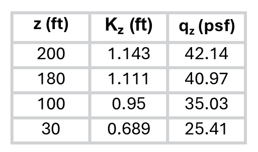
The velocity pressure coefficient and velocity pressure at mean roof height (h = 200 ft) is computed as qh = qz using Kz at mean roof height, h. Thus, Kh = 1.143 and qh = 42.14 psf.
Step 4: Identify the C&C Zone
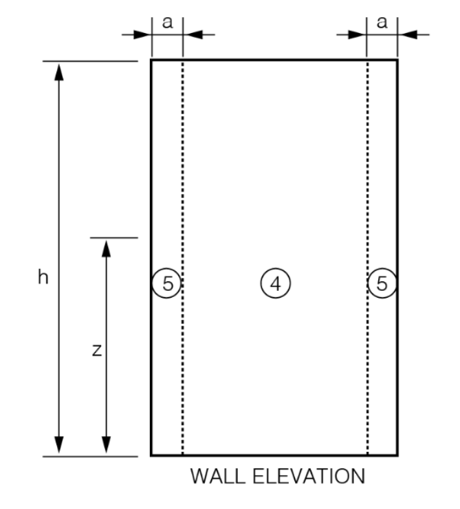
The wind pressure on a window or cladding panel depends heavily on its zone. For walls, ASCE 7-22 defines two primary zones:
- Zone 4: Interior wall area
- Zone 5: Edge zone near corners
Each zone has a different GCp value. Components located within 10% of the least horizontal dimension, a, from a building edge or corner are typically subject to higher uplift or suction pressures and are classified in zone 5.
Step 5: Determine Effective Wind Area (A)
The GCp value is tied to the effective wind area, which represents the tributary area of the component being designed. For windows, this is typically the area of the window itself. Larger components have smaller GCp magnitudes (less severe suction), while smaller components must be designed for more severe pressures.
Our example is utilizing an effective wind area, A, of 50 ft2.
Step 6: Determine external pressure coefficients, +/- GCp
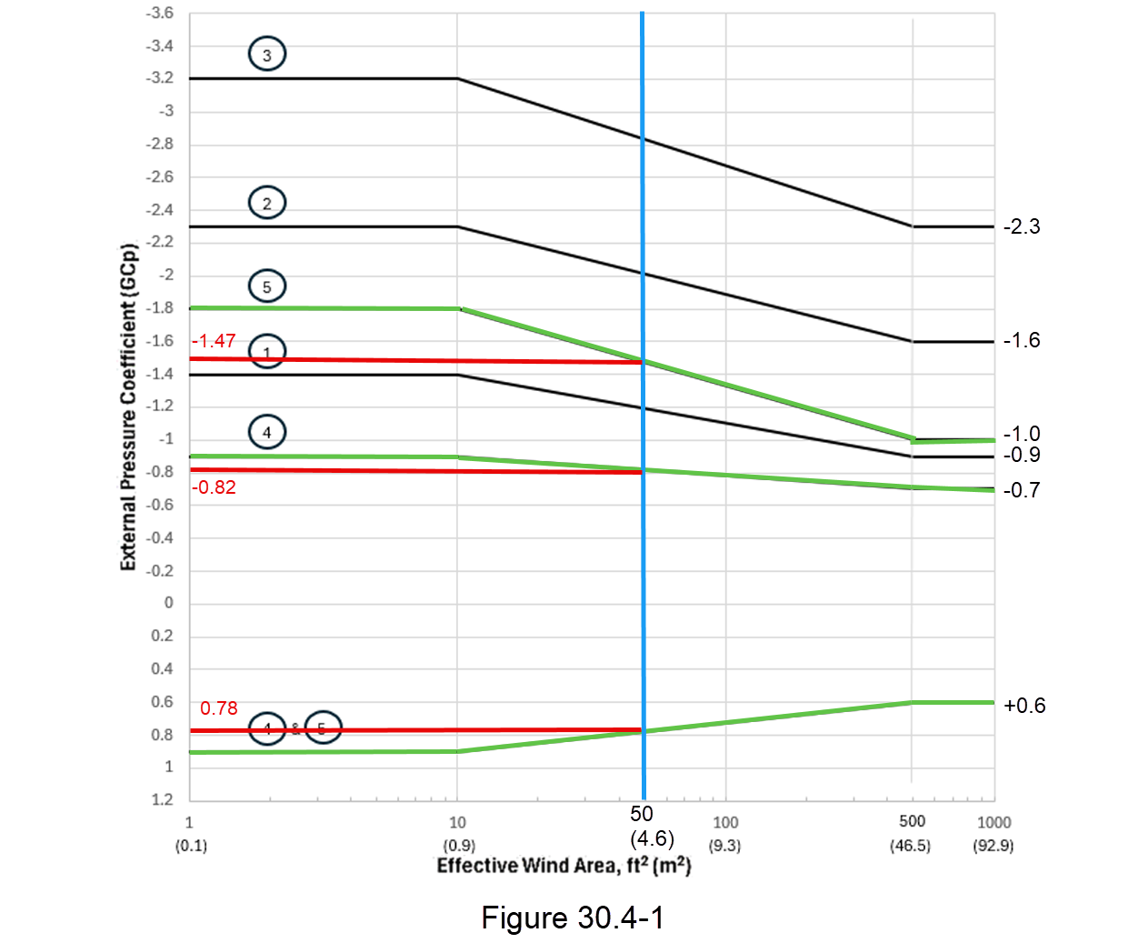
Note: Figure 30.4-1 was revised in Errata 1 Effective September 20, 2024
Using the graph provided in Figure 30.4-1, we will look for the lines labeled with a 4 and 5 representative of the two C&C wall zones we determined in step 4 (green line). We then, enter the graph at our effective wind area along the horizontal axis and follow this until the 4/5 line crosses our effective wind area (blue line). Once we have determined this intersection, we move horizontally to the y-axis to determine our GCp values (red line). The estimated values for each are as follows:
This figure also provides important supplement notes, such as:
- Use qz with positive values of (GCp) and qh with negative values of (GCp)
- Each component shall be designed for maximum positive and negative pressures

Step 7: Calculate C&C Design Wind Pressure
Now we can put everything together to get our design wind pressures on the windows (components and cladding) of our example high-rise building.
We will use the equation 30.4-1: p = q*Kd*(GCp) – qi*Kd*(GCpi)
where:
- q = qz, for windward walls calculated at height z above the ground
- q = qh, for leeward walls, sidewalls, and roofs evaluated at height h
- qi = qh, for windward walls, sidewalls, leeward walls, and roofs
Windward Wall
Combining the definition of this equation with Note 4 from Figure 30.4-1, results in a modified equation 30.4-1 for windward walls of:
p = qz*Kd*(+GCp) – qh*Kd*(+/-GCpi)
where p,min would use +GCpi and p,max would use -GCpi.

Leeward Wall and Sidewall
For leeward walls and sidewalls, the definitions modify equation 30.4-1 to:
p = qh*Kd*(-GCp) – qh*Kd*(+/- GCpi)
where p,min would use +GCpi and p,max would use -GCpi

Combined and Simplified
The windward, leeward, and sidewall classification will change depending on the direction of the wind. This gives us the opportunity to simplify our results in designing our components and claddings for a maximum positive pressure (acting towards the surface—p,max) and a maximum negative or suction pressure (acting away from the surface—p,min) regardless of wind direction.
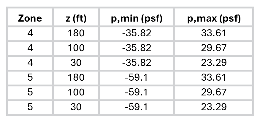
For tall buildings, C&C pressures should be evaluated at multiple elevations, often in story-by-story bands or zones (e.g., every 10 ft or floor level). This means a 30th-floor window and a 100th-floor window of the same size and zone might have very different design pressures, due to increasing qz with height. When calculating C&C pressures evaluated by floor level, it is common practice to use the elevation at the top of the floor for C&C pressure of the entire floor. For further conservatism and simplification, the C&C pressures for the entire building can be evaluated using qh instead of qz when calculating the windward C&C design pressure, which will result in an increase of the maximum positive pressure for the design.
Summary
When determining C&C pressures for a high-rise:
- Use ASCE 7-22 Chapter 30 Part 2 for buildings over 60 ft tall
- Determine design parameters
- Calculate elevation specific design parameters
- Determine external pressure coefficient, GCp, from Figure 30.4-1
- Calculate design wind pressure for each elevation
MecaWind Comparison
Now that we have done the hard work of calculating the components and cladding design wind pressures for the walls of a high-rise buildings, let’s compare how this process looks inside the MecaWind software program (v2531).
To access these results, here is the input form and output form respectively.
