
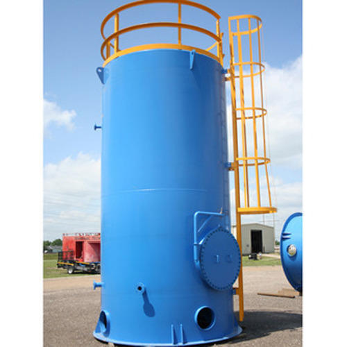
Wind Loads on Tanks

In the ASCE 7-16 publication, new sections were added to address wind loads on tanks, bins, and silos. All three of these structures (tanks, bins, and silos) are handled exactly the same, since all of these structures are basically the same structure but with different names. There are design standards for tanks in specific applications, such as storage tanks for petroleum products, that have specific requirements that should be followed; however, this article will go through the basics of how to calculate wind loads on tanks using the ASCE 7 criteria.
ASCE 7-16 Overview:
A tank is considered an “Other Structure”, and is covered under Section 29.4 of ASCE 7-16. The basic formula is the same as previous versions of ASCE7, and is the following:
F = qz * G * Cf * Af [Eqn 29.4-1]
qz = Velocity pressure evaluated at z
G = gust factor (0.85 if rigid structure with natural freq < 1 Hz)
Cf = 0.63 per Section 29.4.2 (0.25<= H/D <= 4, on ground or columns if
Af = Projected area normal to the wind
Wind Loads on Tanks External Walls:
Section 29.4.2 indicates that if the following criteria are met, then the Drag Coefficient ‘Cf’ can be 0.63.
0.25 <= H / D <= 4
Cylinder is either on ground or supported on columns with c <= H
The standard doesn’t indicate what to do if these conditions are NOT met, but in MecaWind we have taken the approach of using Fig 29.4-1 for a moderately smooth cylinder if these criteria are not met.

Grouped versus Isolated Tanks:
If there is a group of tanks and the center to center spacing is greater than 2 diameters, then the tanks should each be treated as isolated structures. If the center to center spacing is then than 1.25 diameters, then the structures shall be treated as grouped and the wall drag coefficient (Cf) and roof pressures coefficient (Cp) shall be determined per Fig 29.4-6. For spacing between 1.25 and 2 diameters the values should be interpolated.
Roof Pressures:
The roof pressures are dependent upon whether it is an isolated tank or group of tanks.
Isolated – Roof Pressures:
The pressures for roofs are determined from the following equation:
p = qh * (GCp – GCpi) [Eqn 29.4-4]
qh = velocity pressure
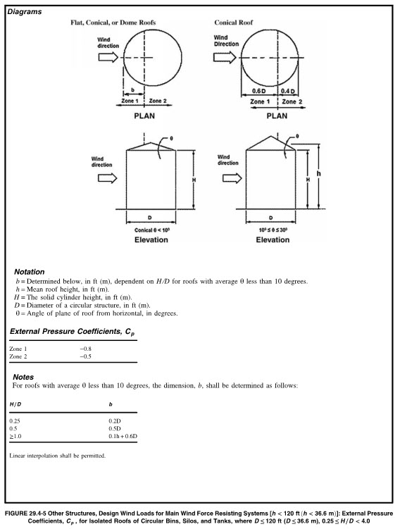
Cp = External pressure coefficient from Fig 29.4-5
GCPi = internal pressure coefficient per section 26.13
G = Gust factor from Section 26.11
All of these terms have been previously introduced, except for the Cp factor, which is taken from Fig 29.4-5. There are two zones – zone 1 and 2 – and the pressure is different for each zone. For roof types that are conical, flat or domed with an angle less than 10 degrees, the Cp is taken from Fig 29.4-5. For domed roofs with a roof angle > 10 Deg, the Cp is taken from Fig 27.3-2.

Grouped – Roof Pressures:
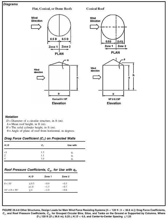
For closely spaced groups of 3 or more tanks, bins or silos with center to center spacing than than or equal to 1.25 x D, the roof pressure and drag coefficient shall be calculated using Fig 29.4-6.
Underside Wind Load on Tank (Floor):
If the tank is elevated above ground by legs, then the pressure on the underside (floor) must be calculated. Section 29.4.2.3 indicates the pressure coefficients to be used as follows:
1/3 <= c/H <= 1 Cp = 0.8, -0.6
0 < c/H <= 1/3 Cp = Interpolate
c/H = 0 Cp = 0, 0
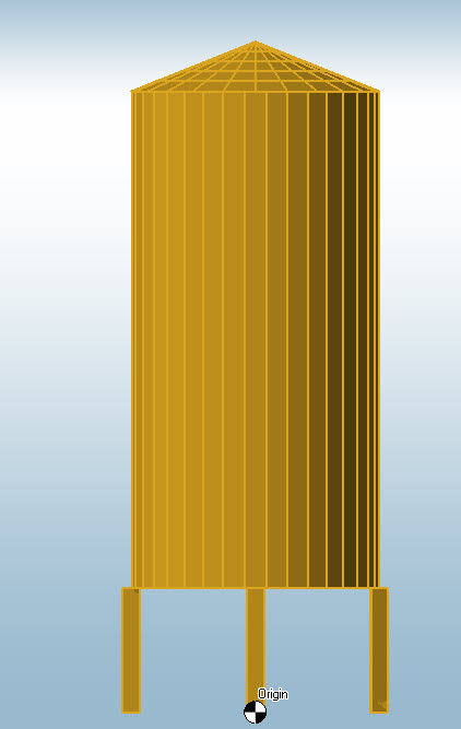
Isolated Tank Example:
Let’s work an example for the wind load on a tank that is isolated and elevated with the following parameters:
V = 120 mph, Exp. C, Category II
Tank Dimensions:
D = 10 ft [3.048 m]
h = 20 ft [6.096 m]
c = 5 ft [1.524 m]
Cone Height = 2 ft
H = 27 ft
H/D = 27 / 10 = 2.7
c/H = 5 / 27 = 0.19
Table 26.11-1 for Exp C:
zmin = 15 ft, zg = 900 ft, Alpha = 9.5
Kzt = 1.0 (No topographic feature)
Kd = 1.0 (per Table 26.6-1)
Ke = 1 (Sea Level)
Calculate Pressure at Top of Roof:
z = 5 ft + 20 ft + 2 ft = 27 ft
Kz=2.01*(27 ft / 900 ft)^(2/9.5) = 0.961
qh = 0.00256*0.961*1*1.0*1*120^2 = 35.42 psf [1.70 KPa]
Calculate Pressure at Top of Cylinder:
z = 5 ft + 20 ft = 25 ft
Kz=2.01*(25 ft / 900 ft)^(2/9.5) = 0.945
qh = 0.00256*0.945*1*1.0*1*120^2 = 34.85 psf [1.67 KPa]
Calculate Pressure at Top of Legs:
z = 5 ft
Kz=2.01*(5 ft / 900 ft)^(2/9.5) = 0.849
qh = 0.00256*0.849*1*1.0*1*120^2 = 31.29 psf [1.50 KPa]
G = 0.85 [Assume rigid structure]
Cf = 0.63 [Sec 29.4.2.1 since H/D = 2]
Roof:
Since cone consider OD to be 1/2 of Cyl OD
Af = 0.5 * 10 ft * 2 ft = 10 sq ft [0.929 sq m]
Cf = 0.63
F = 35.42*0.85*0.63*10 = 190 lbs [845 N]
Cylinder:
Af = 10 ft * 20 ft = 200 sq ft [18.58 sq m]
Cf = 0.63
F = 34.85*0.85*0.63*200 = 3732 lbs [16,600 N]
Legs:
Af = 1 * 5 = 5 sq ft [1.524 sq m]
Cf = 1.367 [h/D = 5/1 = 5, Fig 29.4-1]
F = 31.29*0.85*1.367*5 = 182 lbs [809 N]
Flegs = 182 lbs x 4 legs = 728 lbs [3238 N]
Ftotal = 190 + 3732 + 728 = 4,650 lbs [20,684 N]
Calculate Wind Load on Roof:
Fig 29.4-5 with H/D = 2 ==> b = 01*H + 0.6*D = 0.1*27+0.6*10 = 8.7 ft
Zone 1 (0 to 8.7 ft) : Cp = -0.8
Zone 2 (8.7 ft to 10 ft): Cp = -0.5
h = 26 ft
Kh = 2.01*(26/900)^(2/9.5) = 0.953
qh = 0.00256*0.953*120^2 = 35.14 psf [1.68 Kpa]
G = 0.85
GCPi = +/-0.18 (Enclosed)
Zone 1: p = 35.14 * (0.85*(-0.8) – (+0.18)) = -30.22 psf [1.45 KPa]
Zone 2: p = 35.14 * (0.85*(-0.5) – (+0.18)) = -21.26 psf [1.02 KPa]
Wind on Underside (Floor):
c/H = 0.18 –> Sec 29.4.3 Interpolating gives Cp = 0.6, -0.45
p = 35.14 * (0.85*0.6 – 0.18) = 11.6 psf [0.56 KPa]
p = 35.14 * (0.85*0.6 + 0.18) = 24.25 psf [1.16 KPa]
p = 35.14 * (0.85*-0.45 – 0.18) = -19.77 psf [0.95 KPa]
p = 35.14 * (0.85*-0.45 + 0.18) = -7.12 psf [0.34 KPa]
Conclusions:
The calculations for wind loads on tanks can be performed manually using the criteria provided in Section 29.4.2, but as you can see there is some work involved with performing these calculations. The same calculations can be performed with relative ease using the MecaWind software. Here is the MecaWind Input File associated with the example and here is the Output File.