
Components & Cladding Zone Graphics
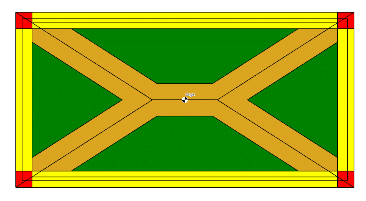
The image above is NOT the Jamaican flag; it is actually a graphical representation of the Components and Cladding (C&C) zones for a hipped roof. ASCE 7 has figures that define the C&C and the zones that are applicable for various roof types. The relative dimensions of those zones are based on parameters that are dependent upon the dimensions of the building. Based on the specific dimensions of the building, there are instances where the scale of the zones may not be obvious from looking at the typical figure, or some zones could be physically impossible to achieve based on the building dimensions. This article will provide an example to show how that could happen.
Building with Flat Roof
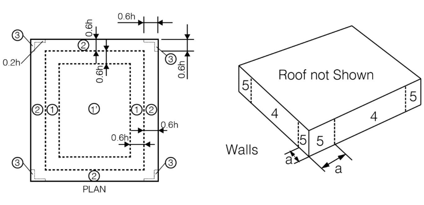
A roof with a slope of ≤ 7° is considered “flat” and follows ASCE 7-22 Fig 30.3-2a, which is shown below.
If we consider a building that is 25′ tall with a flat roof and 100 ft x 100 ft plan dimensions, then using the C&C Graphic option in MecaWind produces the following scaled graphic. Please note that the dimensions have been hidden so that the graphic would be less cluttered.

In this example, we have chosen dimensions so that all zones are visible, and the graphic looks similar to that depicted in Figure 30.3-2a.
Zone 1′ Very Small
Referring to Figure 30.3-2a above, it is apparent that the width of the zones is dependent on 0.2•h and 0.6•h. The height (h) in the example above is 25 ft. Let’s see what happens if h = 40 ft. The Zone 3 corners get larger, and Zone 1′ becomes very small.

Zone 1 & 1′ Eliminated
Consider a flat-roof building that is 60 ft tall and has plan dimensions of 70 ft x 70 ft. Now, 0.6•h = 36 ft and 0.2•h = 12 ft. These dimensions cause Zone 1 and Zone 1′ to be completely eliminated, and the corner Zone 3 areas become so large that they touch each other. This is a good example of why the C&C Graphic option can be so useful; it would not be obvious from looking at Fig 30.3-2a that Zones 1 and 1′ are not possible.

C&C Validation
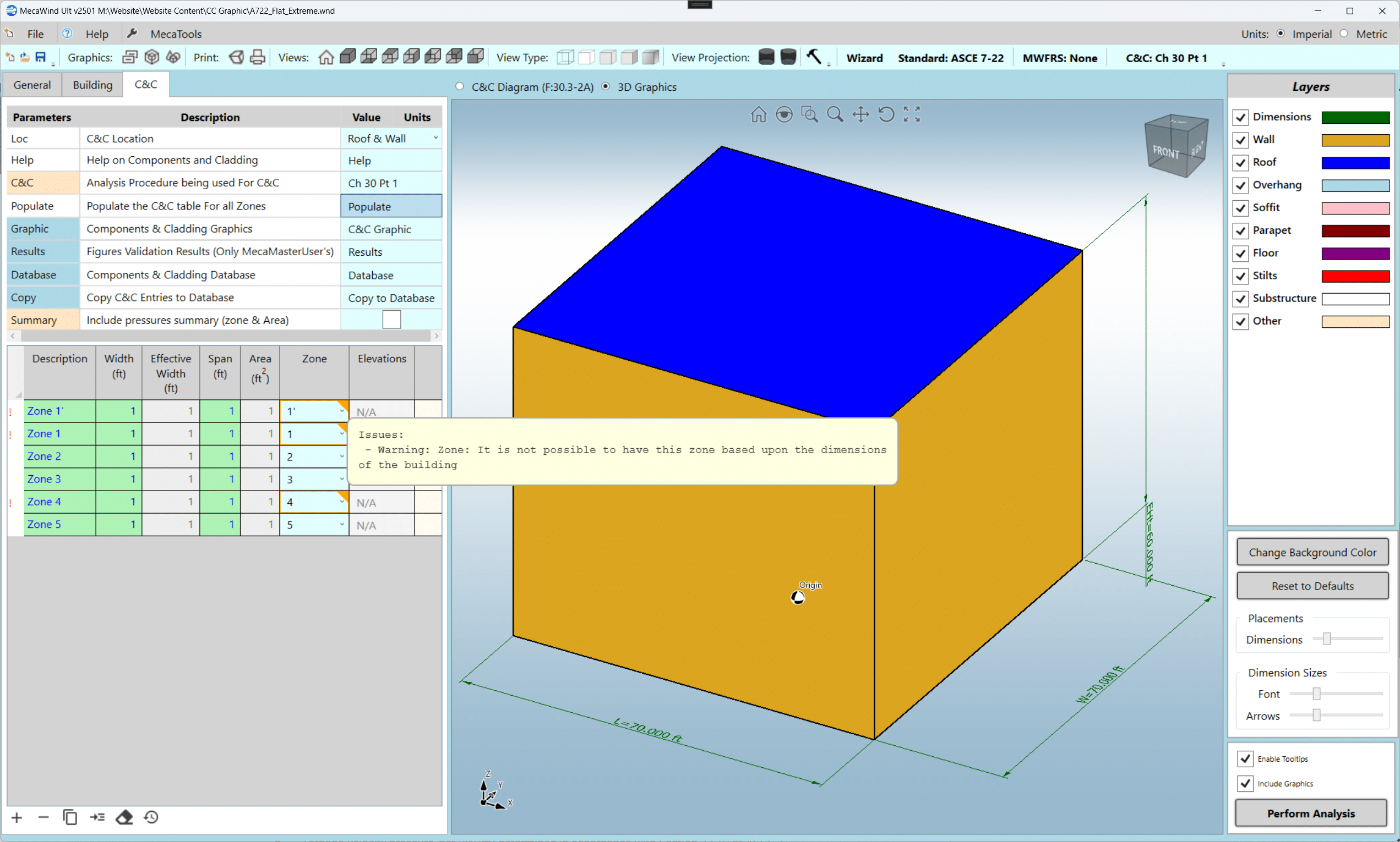
As seen in the last example, Zones 1 and 1′ are not applicable. MecaWind (Ultimate version only) will recognize that these zones cannot exist, and if you try to use one of them, it will issue a warning to the user. In the screenshot below, there are warnings for Zones 1, 1′, and 4 since none of these zones can exist for this particular set of inputs. Although this example does not include overhangs, this feature can also indicate when a zone will be applicable for the overhang as well.
Populate Valid Zones Only
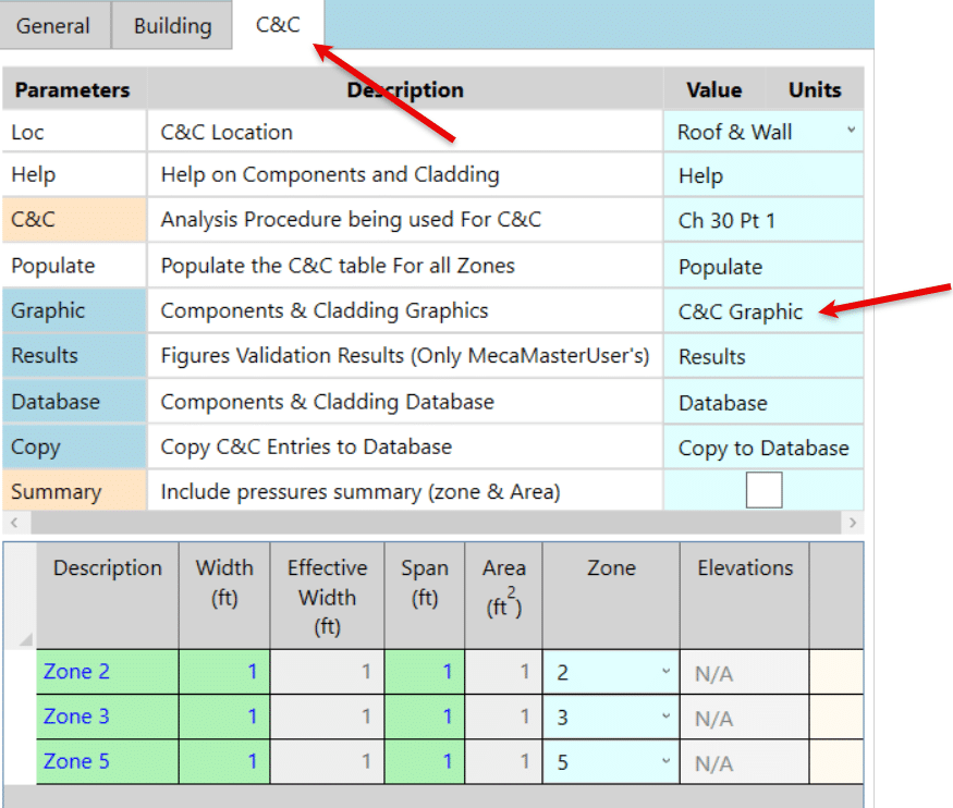
When setting up C&C zones, the user has the option to populate one entry for every zone by clicking the Populate option. When using the Ultimate version, the user now has the option to populate ONLY those zones that are valid. This is done by checking the “Only Show Valid Zones” checkbox. In the example above, Zones 1, 1′, and 4 were not possible, so if the “Only Show Valid Zones” checkbox is checked, those zones would not be populated.

Conclusion
We believe the C&C Zone Graphic is a valuable addition to the MecaWind application. This option exists only in the Ultimate version of the application and can be accessed on the C&C Tab by clicking the C&C Graphic Button.
In this article, we have used a “Flat” roof as an example, but the same C&C Graphic option exists for other roof types and figures included in the ASCE 7 standard. When a building is more complex, such as with an “L-Shaped” building or an elevated building with a floor, the C&C graphic for each location can be selected to show the simplified C&C graphic for that location. For example, if it is an L-Shaped building, the user would select to see the C&C graphic for End 1 and then End 2 to display each end of the building.

The C&C Graphic option is only available in the Ultimate version of MecaWind and was added to v2501 of the software. If you would like more information about MecaWind Ultimate, please refer to this page on our website. Feel free to contact us at [email protected] with any questions or comments.