Stack Supported on Structure

There are many real-world examples of steel stacks or chimneys supported on top of another structure. This could be a space frame, building or another piece of equipment such as a heater. The supporting structure can introduce flexibility to the system, and this article explains how to consider that flexiblity in the analysis.
Can the supporting structure be ignored?
It certainly could make our structural analysis simpler if we could ignore the supporting structure and just treat it as rigid. The question is whether ignoring it will negatively impact the accuracy of our structural analysis. This isn’t always a simple question to ask. The primary question is whether the supporting structure could be considered to be “Rigid” or if it introduces some flexibility. There are two (2) questions that need to be answered:
1) Does my supporting structure overall appear large compared to the stack and can be considered Rigid?
2) Does the localized point where the stack and supporting structure connect appear to be robust enough to be Rigid?
These questions can be somewhat subjective. There are times when an experienced structural engineer can look at a structure and conclude that it is clearly a rigid structure.
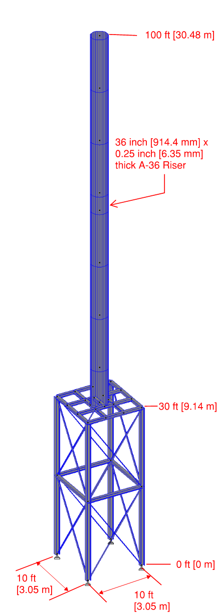
This isn’t anything definitive, but a rule of thumb I have used is if the supporting structure has a height to least horizontal ratio of 4 or less, then I think of it as being rigid. For example, lets assume we have a 70 ft [21.34 m] tall stack and it is supported on a 30 ft [9.14 m] tall structure making the top of stack 100 ft [30.48 m] above grade. The structure has a 10 ft [3.05 m] x 10 ft [3.05 m] footprint. If we take the ratio of height to least horizontal dimension, the ratio is 100 ft/10 ft = 10. This is much greater than our rule of thumb of 4, and so this structure would not be safe to assume as rigid.
Let’s consider a real world example?
Let’s consider a real world example of a structure. The structural information is as follows:
• Stack Height Above Grade = 100 ft [30.48 m]
• Stack Diameter = 36 in [914.4 mm]
• Structure Height = 30 ft [9.14 m]
• Structure Width = 10 ft [3.05 m]
This stack is completely supported on the space frame, the weight is transferred to the supporting structure as well as all lateral loads. The support frame is a braced frame and each of the 4 columns have a pinned support that restrains the base from translation in the X, Y and Z directions. Rotation is allowed at the support points.
When analyzing the stack in MecaStack, we are not able to model the supporting space frame structure. The questions we have for this analysis of the stack are as follows:
1) Can we assume the base of the stack is rigid without losing much accuracy?
2) Does including the supporting space frame in the analysis affect our deflection calculations?
3) Does including the supporting space frame in the analysis affect the dynamic behavior of the stack?
To answer these questions we will work through a typical example of a stack supported on a support structure.

Model 1: Stack and Support Structure Analyzed in StaadPro:
We start with an analysis that is going to give the most accurate results where we have considered the stack and support structure in a single model analyzed in STAAD.Pro. The structure is a space frame with wide flange (I-Beams) columns and the braces are angles which are treated as truss members. In the analysis we applied 100 lb/ft [1460 N/m] as a uniform load to just the stack structure, no lateral load was applied to the supporting structure.
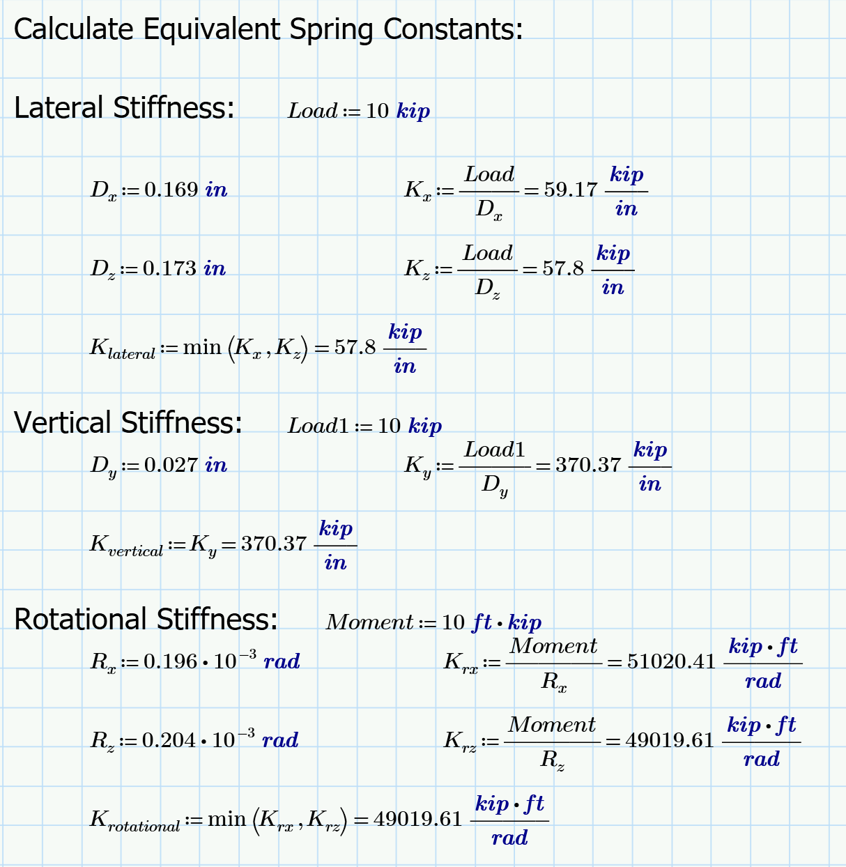
We applied “Dummy” forces and moments in different load cases in order to determine effective spring constants for the supporting structure. Dummy forces of 10,000 lbf [44,500 N] in the X, Y and Z direction at the bottom node of the stack where it connects to the supporting structure. We also applied dummy moment loads of 10,000 ft•lbf in the Mx and Mz directions at this same node. We did not consider any torsional moment (My).
The StaadPro file used for this analysis can be downloaded from this link.

Model 2: Stack with a Rigid Support:
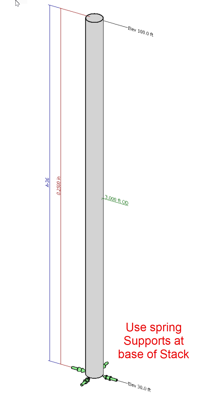
This model is a simplified model where we assume a stack with a rigid base in the MecaStack software. We will make a stack that is 100 ft [30.48 m] Overall Height with a base for the stack at 30 ft [9.14 m]. On the stack we place the equivalent of 100 lb/ft [1460 N/m] uniform load on the stack. We use a shape factor of 1 and a pressure of 33.33 psf [1596 Pa], since the stack is 3 ft [0.914 m] in Diameter the load becomes 33.33 psf*1.0*3 ft = 100 psf [1460 N/m].
The MecaStack file used to perform this analysis can be downloaded at this link.

Model 3: Stack with Spring Support?
Our next model is a hybrid combination of Model 1 and 2. This model was also performed in the MecaStack software, but rather than a fixed base (as assumed in Model 2) we calculate spring constants using the Dummy load cases we used in the StaadPro model created in model 1. The MecaStack software doesn’t allow us to model the supporting structure and so we are attempting to determine if the supporting structure could be reasonably approximated using a spring support.
The spring constants were taken by using each of the dummy forces/moments and determining the resulting deflection or rotation from the staadpro model, and then calculating a spring constant. The deflections and rotations are taken at the base of the stack, which is the same point used for applying the forces/moments. Please note that since we are using wide flange columns for the supporting structure, the stiffness is not identical in each direction and so we get slightly different deflections/rotations in the X and Z directions. We evaluate both and then use the lowest value in our MecaStack analysis.


Using these spring constants we then created a model in MecaStack with a fixed support with springs matching these constants. This MecaStack file can be downloaded at this link.

Model Comparison:
Now that we have these three (3) different models lets compare the results. Our Model 1 was the StaadPro model and the model which we consider to be the most accurate and so it will be our baseline. Model 2 was a very simplified model where we considered the base of the stack to be rigid and we completely disregarded the stiffness of the supporting structure. In Model 3 we tried to use a simple model of just the stack and account for the supporting structure by using equivalent springs at the support. In our analysis we compared the deflection at the top of the stack and the frequency of the stack for modes 1 through 3. A summary of the results are included below.

We can see from the data that Model 2 with the rigid support has very poor correlation to Model 1. The Model 2 deflection is 51% less than it should be and the first mode frequency is 45% higher than Model 1. Model 3 (with the spring support) gives reasonably accurate results for the deflection and mode 1 of the natural frequency. The mode 2 natural frequency is 19% high, and mode 3 (and higher) starts seeing significant differences when compared to Model 1.
When we look deeper into the analysis we can better understand why mode 2 and higher start becoming less accurate. Mode 1 vibration is cantilever vibration and this mode has good correlation. Mode 2 is double curvature and you can see from the comparison below that the support structure has more involvement in the deflected mode shape. We approximated this base structure with three (3) linear springs, and so this is not completely accurate for higher modes of vibration.

The question now is does it matter that our mode shapes for 2 and higher are not highly accurate? The answer is that it depends upon the situation. If you are performing a seismic analysis based upon a response spectrum analysis, then you will need accurate frequencies and mode shapes; however, seismic doesn’t control most stacks. Wind is usually the controlling lateral load case. In most cases when wind controls the stack then the second mode inaccuracy won’t be too impactful. We only use these higher modes to check wind induced vibration (vortex shedding), and typically mode 2 and higher wouldn’t be a concern anyway. Mode 2 in our example was off by 19%, and so it would still give you a rough idea whether the mode 2 is a problem for Vortex Shedding. If your stack is right on the border of having a Vortex shedding problem (refer to this article for more discussion on this topic), then maybe you need to investigate this further. If you are well above the upper limit, then the inaccuracy in Mode 2 and higher is probably of little concern.
Conclusion:
The MecaStack software can make simple work of analyzing a steel stack, but when that stack is supported on another structure then things get more complicated. In the example that we worked through in this article we found that approximating the supporting structure with equivalent springs is a reasonable approximation for many situations. This simplification does lose accuracy for higher mode frequencies, but in most instances this is not of serious concern. In the cases where it is impactful, then more analysis can be taken with those structures.
In the event that you have a structure with varying stiffness in different directions then re-run the analysis by using a different spring constants and find the worst case. Typically the lowest stiffness will be the worst case.
