
Wind Loads at Elevations

In designing structures we typically want to calculate wind loads at elevations that are important for the structure. Some tall buildings have each floor being the same height and other structures such as the Sagrada Familia Cathedral in Barcelona which is completely unique and has no two floors the same height. Please don’t ask me how to design the Sagrada Familia structure (or similar structure) using MecaWind, but I can tell you how to calculate the wind pressures on the Main Wind Force Resisting system at specific elevations.
Higher Wind Loads at Elevations:
The wind velocity increases as the elevation increases, this is shown in the corresponding graphic. Near ground level there are obstructions such as houses and buildings and trees, and these obstructions give the surface of the earth a higher roughness and decrease the velocity of the wind. In areas near open fields or water, the obstructions are fewer and the reduction of wind velocity is less. This is all taken into account in ASCE 7-16 Table 26.10-1 ‘Velocity Pressure Exposure Coefficients, Kh and Kz’.

Example:
Lets say we have a building that is 120 ft tall, and has a wind velocity of 140 mph Exposure C.
V = 140 mph
Kzt = 1 (No topography features)
Kd = 0.85 (Building for MWFRS Design)
Ke = 1.0 (Sea Level)
Kz = 2.01*(120/900)^(2/9.5) = 1.315
(Note that Kz using formula is slightly different 1.315 vs 1.31 when compared to the table values, but we use the formula because that is what is used in MecaWind).
qz = 0.00256*1.31*1*0.85*1*140^2 = 55.87 psf

MWFRS Mean Roof Height:
The most conservative option when calculating wind loads by elevations is just to use the Mean Roof Height for the Main Wind Force Resisting System (MWFRS) design. In our previous example this would be using the 120 ft mean roof height to calculate the wind pressure, and then using that pressure for the entire design. For the above example, that would be using 55.87 psf for everything.

MWFRS Automatic Elevations:
If a building has every floor height the same, then using the automatic elevations is the best option for determining wind loads at elevations important to the structure. In the corresponding example, each flor is 15 ft high, and so we would like to get the wind pressures at 15 ft, 30 ft, etc.. up to the top of the structure. This would be calculating the pressure at every floor of the structure. This is handled in MecaWind by specifying the Automatic Elevations and then entering a value of 15 ft.

Using MecaWind the pressure at each floor elevation is highlighted below.


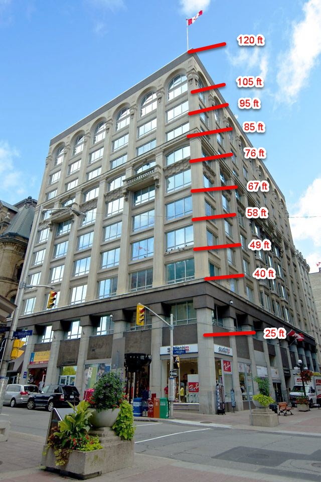
MWFRS Manual Elevations:
When the floors are not all the same height, then the manual elevations option should be selected. Each elevation where the wind pressure is desired is manually entered.


Components and Cladding Ch 30 Pt 3:
There is only one method used for Components and Cladding (C&C) which considers the wind loads by elevations and that is ASCE 7-16 Chapter 30 Part 30 for Buildings > 60 ft. When considering windward walls the pressure can be calculated based upon the mean roof height to be conservative; however, the standard does allow the qz to be based upon the actual elevation for windward walls. This is of importance when the building is considered partially enclosed because the internal pressure can be based upon the qz at the level of the highest opening in the building that could effect positive internal pressure. In a tall building this can be a significant savings. For example, if you had a 300 ft building in Exposure B where the highest opening is 60 ft, then the difference between qz at 300 ft and qz at 60 ft would represent a 59% increase in internal pressure.
For buildings sited in wind-borne debris regions that do not have impact-resistant glazing or that are not protected with a impact-protective system then the qi should be treated as an opening.

MecaWind gives the user some options with regard to calculating the wind pressures on C&C when following Chapter 30 Part 3:
Use Mean Roof Height:
This is the most conservative option and will use the mean roof height for all pressure calculations:
Automatically Increment Elevations:
This will automatically increment the elevation by the amount specified by the user. For example, if an increment of 10 ft is specified then the C&C pressures would be calculated at every 10 ft.
Manually Specify Elevations:
The user will be allowed to enter an elevation or elevations at which C&C pressures are to be calculated.
Please note that this option will only appear on the C&C input screen when Chapter 30 part 3 is selected, and it is only applicable to zones on the wall (Zone 4 and 5).

MecaWind Input Files:
Here is a link to the MecaWind input file used for the calculations in this article, you will need to change the elevation entry to the appropriate method (Mean Height, Automatic or Manual) depending upon which values you are trying to replicate.