
Wind Loads on Solid Signs

While in a dream driving down the highway, I saw the image shown above and I thought to myself that this must be a sign. I was correct, it was a sign. A sign that we need to write an article explaining how to calculate wind loads on solid signs. Although this should be a relatively simple calculation, we have all learned that not much in ASCE 7 is truly simple. Let’s go through the details of calculating wind loads on solid signs.
Wind Load Formula:
Wind loads on Signs and Freestanding walls is covered in ASCE 7-16 by Section 29.3 “Design Wind Loads: Solid Freestanding Walls and Solid Signs”. The formula is very simple and one we have seen many times in ASCE 7-16, with the only exception being the introduction of the Cf, which is a net force coefficient taken from Figure 29.3-1.

This method applies to a “solid” sign. A sign or freestanding wall is considered to be solid if the openings comprise less than 30% of the gross area of the sign or freestanding wall. Forces on solid signs with openings shall be permitted to be multipled by the following reduction factor:
Reduction Factor = 1 – (1-e)^1.5
e = Solidity Ratio = Solid Area / Gross Area
ASCE 7-16 Figure 29.3-1 Force Coefficients Cf
The biggest task in calculating wind loads on signs and freestanding walls is to determine the force coefficient from Figure 29.3-1. In this figure there are up to three different loading conditions that may need to be considered, Case A, B, and possibly C.

In figure 29.3-1 it states that Case A and B must be considered for all S/h < 1, which basically covers the range of nearly all possiblities. Case C must only be considered when B/s>= 2, which means it must only be considered if the sign width is at least double its height.
Signs Supported on Columns:
When the sign is supported on columns, we not only have the wind load on the sign but also wind acting on the columns. To calculate the wind loads on the column we follow the criteria for wind loads on chimneys. Fortunately we wrote an article that explains that approach, and that information can be found here.
Using the shape factors for a chimney we calculate the wind loads acting on the columns.

Signs attached to Walls:
When a sign is attached to a wall, then Section 29.3.2 indicates that the internal pressure coefficient (GCpi) be set to zero and the wall pressure be used. This same criteria applies if the sign is attached to the wall but not in direct contact with the wall, as long as the gap between the wall and sign is not more than 3 ft [0.9 m] and the edge of the sign is at least 3 ft [0.9 m] in from free edges of the wall (side and top edges and bottom edges of elevated walls).

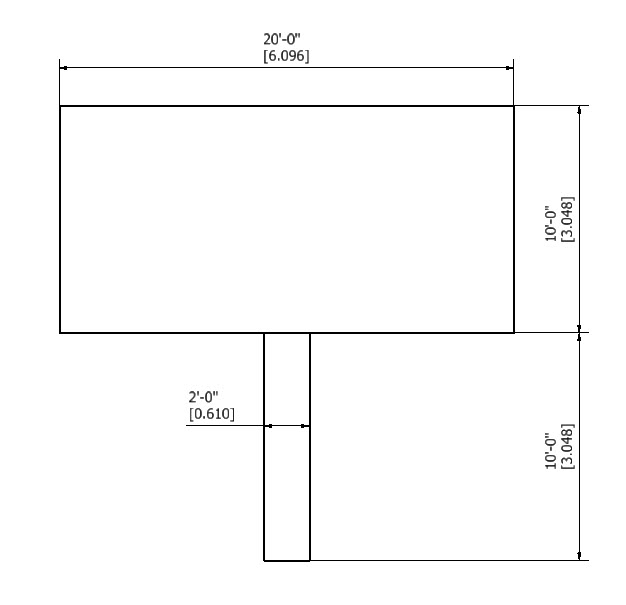
Wind Load on Solid Sign Example:
Let’s work an example to illustrate this method. We have an elevated sign that is 10 ft [3.048 m] high by 20 ft [6.096 m] wide. It is on a round support that has a 2 ft [0.61 m] outer diameter and is moderately smooth.
ASCE 7-16, 120 mph, Exp. C, Category II
Mean Building Structure Height (h) = 20 ft
Table 26.11-1 for Exp C –> zmin = 15 ft, zg = 900 ft, Alpha = 9.5
z = 20 ft (Mean roof height)
Kh=2.01*(20 ft / 900 ft)^(2/9.5) = 0.902
Kzt = 1.0 (No topographic feature)
Kd = 0.85 (per Table 26.6-1)
Ke = 1 (Sea Level)
Calculate Pressure at Mean Roof Height:
qh = 0.00256*Kh*Kzt*Kd*Ke*V^2
= 0.00256*0.902*1*0.85*1*120^2 = 28.26 psf [1.353 KPa]
B = 20 ft, s = 10 ft, h = 20 ft
B/s = 20 ft / 10 ft = 2.0
s/h = 10 ft / 20 ft = 0.5
Case A Wind Loads:
Referring to Figure 29.3-1 for B/s = 2 and s/h = 0.5 we get a Force coeffient of 1.7

Case A force becomes:
Fa = qh * G * Cf * As = 28.26*0.85*1.7*(10*20) = 8167 lbs [36.34 KN]
Case B Wind Loads:
Case B wind loads are identical to Case A, except that they are applied at an offset from the center of the face (see diagram). Since the sign is not double-faced, we don’t have the special conditions indicatedin Fig 29.3-1 Note 3. That means the eccentricity for the sign becomes:
Dx = 0.2*B = 0.2*20 ft = 4 ft [1.219 m]
Fb = Fz = 8187 lbs [36.34 KN]

Case C Wind Loads:
Since B/s = 2 which is >= 2, we must consider Case C. We refer again to Figure 29.3-1 and obtain the force coefficients for the case C.

From the table we determine the following Force Coefficients:
Cf (0 to s) = 2.25 (0 to 10 ft)
Cf (s to 2s) = 1.5 (10 ft to 20 ft)
With these values we can then calculate the forces:
F (0 to 10 ft) = qh*G*Cf*As = 28.26*0.85*2.25*(10*10) = 5405 lbs [24.05 KN]
F (10 to 20 ft) = qh*G*Cf*As = 28.26*0.85*1.50*(10*10) = 3603 lbs [16.03 KN]
The forces are applied at the center of each of the spans.

Wind on Support Columns:
Now we calculate the wind load on the support columns using the chimney criteria.
h = 20 ft [6.096 m]
D = 2 ft [0.6096 m]
qh = 28.26 psf [1.353 KPa]
D*qh^0.5 = (2)*(28.26^0.5) = 10.63
h/D = 20/2 = 10
Cf = 0.617 (Using interpolation)
F = qh * G * Cf * A = 28.26*0.85*0.617*(2*10) = 296 lbs [1.319 KN]

Same Example Using MecaWind
Now we perform the same set of calculations using the MecaWind software. The input file can be obtained here, and the output file here. The output results match exactly those which we have calculated here.
