Components and Cladding Example

This article provides a Components and Cladding (C&C) example calculation for a typical building structure. We will first perform the calculations manually, and then show how the same calculations can be performed much easier using the MecaWind software.
What is Components and Cladding?
ASCE 7-16 defines Components and Cladding (C&C) as: “Elements of the building envelope or elements of building appurtances and rooftop structures and equipment that do not qualify as part of the MWFRS (Main Wind Force Resisting System).” In simple terms, C&C would be considered as windows, doors, the siding on a house, roofing material, etc..

Example Problem:
We will use ASCE 7-16 for this example and the building parameters are as follows:
Building Eave Height: EHt = 40 ft [12.2 m]
Building Length: L = 200 ft [60.96 m]
Building Width: W = 100 ft [30.48 m]
Roof Type: Monoslope with 1:12 Slope
Enclosure Type: Enclosed
Elevation: Job site is at sea level
Wind Speed: V = 150 mph [67.1 m/s]
(Based upon Category III)
Exposure: C (Open Terrain)
Topography: Flat, no topographic features

Effective Area:
In order to calculate the wind pressures for each zone, we need to know the effective area of the C&C. To determine the area we need the Width and Length:
Length = Span of the component
Width = The effective width of the component which need not be less than 1/3 of the span length.
As an example, a roof joist that spans 30 ft and are spaced 5 ft apart would have a length of 30 ft and the width would be the greater of 5 ft or 30 ft / 3 = 10 ft. In this case the 1/3 rule would come into play and we would use 10ft for the width.
Eff Area = 30 ft x 10 ft = 300 sq ft
(Note: MecaWind makes this adjustment automatically, you just enter the Width and Length and it will check the 1/3 rule)
When calculating C&C pressure, the SMALLER the effective area the HIGHER the wind pressure.
Most of the figures for C&C start at 10 sq ft [0.9 sq m] and so for the purpose of this example we will consider an effective area of 10 sq ft for all wall and roof wind zones. This will give us the most conservative C&C wind pressure for each zone.
Chapter 30, but Which Part?
Chapter 30 of ASCE 7-16 provides the calculation methods for C&C, but which of the seven (7) parts in this section do we follow? We just have to follow the criteria for each part to determine which part(s) our example will meet. To do this we first need our mean roof height (h) and roof angle.
Roof Angle = arctan(1/12) = 4.76 Deg
Sec 2.62 defines the mean roof height as the average of the roof eave height and the height to the highest point on the roof surface, except that, for roof angles less than or equal to 10 deg, the mean roof height is permitted to be taken as the roof eave height.
Since our Roof Angle (4.76 Deg) <= 10 Deg, then we can take h as the eave height (EHt).
h = EHt = 40 ft [12.2 m]
The other determination we need to make is whether this is a low rise building. To be considered a low rise, the building must be enclosed (this is true), the h <= 60 ft [18] (this is true) and the h<= least horizontal width. Our least horizontal dimension is the width of 100 ft [30.48] and our h is less than this value, so this criteria is met as well. Therefore this building is a low rise building.
Using all of this criteria, we can then determine that the only two methods of Chapter 30 where we meet all criteria are Part 1 and 4 (see chart).

Chapter 30 Part 1:

We now follow the steps outlined in Table 30.3-1 to perform the C&C Calculations per Chapter 30 Part 1:
Step 1: We already determined the risk category is III
Step 2: V = 150 mph
Step 3: Determine Wind Load Parameters
Kd = 0.85 (Per Table 26.6-1 for C&C)
Kzt = 1 (There are no topographic features)
Ke = 1 (Job site is at sea level)
GCpi = +/-0.18 (Tabel 26.13-1 for enclosed building)
Step 4: Determine Velocity pressure exposure coefficient
zg = 900 ft [274.32] (Table 26.11-1 for Exposure C)
Alpha = 9.5 (Table 26.11-1 for Exposure C)
Kh = 2.01*(40 ft / 900 ft)^(2/9.5) = 1.044
Step 5: Determine velocity pressure
qz = 0.00256*Kh*Kzt*Kd*Ke*V^2
= 0.00256*(1.044)*(1)*(0.85)*(1.0)*(150^2) = 51.1 psf
Step 6: Determine External Pressure Coefficient (GCp).

We are looking at pressures for all zones on the wall and roof. For the wall we follow Figure 30.3-1:
For 10 sq ft, we get the following values for GCp. Note 5 of Figut 30.3-1 indicates that for roof slopes <= 10 Deg that we reduce these values by 10%, and since our roof slope meets this criteria we multiply the figure values by 0.9
Zone 4: GCp = +1.0*0.9 = +0.9 / -1.1*0.9 = -0.99
Zone 5: GCp = +1.0*0.9 = +0.9 / -1.4*0.9 = -1.26

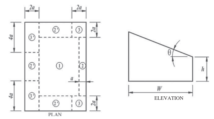
A Monoslope roof with a slope between 3 deg and 10 deg follows Fig 30.3-5A. For each zone, we get the following values:
Zone 1: GCp = +0.3 / -1.1
Zone 2: GCp = +0.3 / -1.3
Zone 2′: GCp = +0.3 / -1.6
Zone 3: +0.3 / -1.8
Zone 3′: +0.3 / -2.6

Step 7: Calculate wind pressure
We can then use all of these values to calculate the pressures for the C&C. Since we have GCp values that are postive and negative, and our GCpi value is also positive and negative, we take the combinations that produce the largest positive value and negative value for pressure:
p1 = qh*(GCp – GCpi)
= 51.1 * (0.3 – (-0.18)) = 24.53 psf (Zone 1)
p2 = 51.1*(-1.1 – (+0.18)) = -65.41 (Zone 1)
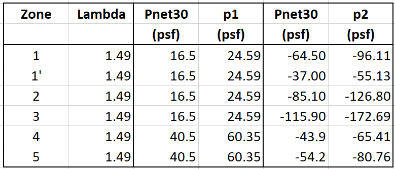
The calculations for Zone 1 are shown here, and all remaining zones are summarized in the adjacent tables.
These pressures follow the normal ASCE 7 convention, Positive pressures are acting TOWARD the surface, and Negative Pressures are acting AWAY from the surface.

Chapter 30 Part 4:
Chapter 30 Part 4 was the other method we could use. This is considered a “Simplified” method and is supposed to be easier to calculate by looking up values from tables. Using the same information as before we will now calculate the C&C pressures using this method.
Step 1: The category is III
Step 2: V = 150 mph
Step 3: Wind load parameters are the same as earlier
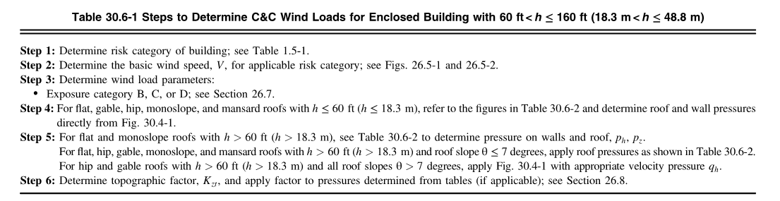
Step 4: For walls and roof we are referred to Table 30.6-2.

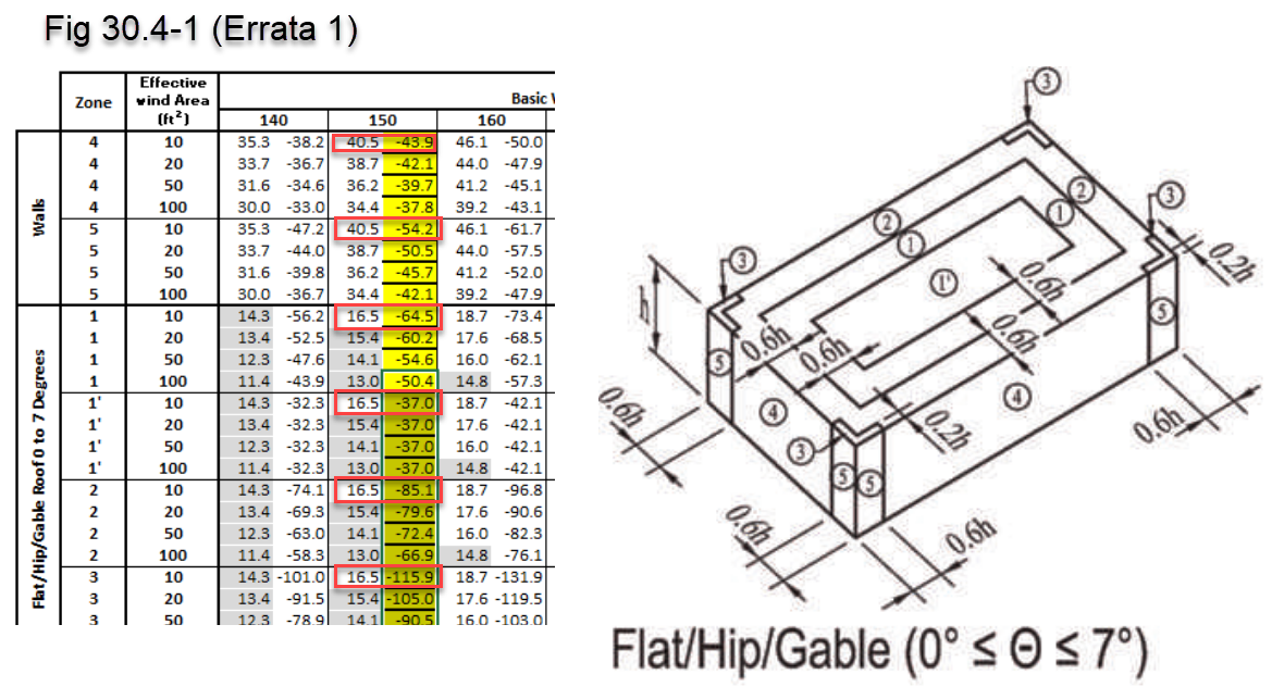
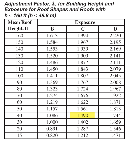
Referring back to Table 30.6-2, it indicates in note 5 that when Fig 30.4-1 applies then we must use the adjustment factor Lambda for building height and exposure.
Referring to this table for a h = 40 ft and Exposure C, we get a Lambda value of 1.49. This value is then multiplied by the value obtained from Fig 30.4-1.