
Wind on Rooftop Structures and Equipment

ASCE 7 has a method for calculating wind loads on rooftop Structures and equipment for buildings, and this article will describe that method. Fortunately, the method is relatively straight forward, not too complicated, and is covered in ASCE 7-16 Section 29.4.1
What type of Rooftop Equipment?
In section 29.4.1 of ASCE 7, it coveres all rooftop structures and equipment EXCEPT solar panels and structures identified in section 29.4 (chimneys, tanks, open signs, single-lane open frames, and trussed towers). We have covered the method for calculating the wind load on solar panels in a separate article. The most common rooftop equipment that would fit this criteria would be Heating Ventilation and Air Conditioning (HVAC) units.

Calculating Lateral Force (Fh):
The lateral force acting on the equipment is calculated using equation 29.4-2. An corresponding excerpt from ASCE 7-16 Sec 29.4.1 is shown with Equations 29.4-2. This is a very simple equation made up of the terms GCr, qh and Af.
The equation is simple, with the most complicated aspect being that the value of GCr is dependent upon Af, and if 0.1*B*h < Af < B*h then we must determine GCr through linear interpolation.

Example Problem:
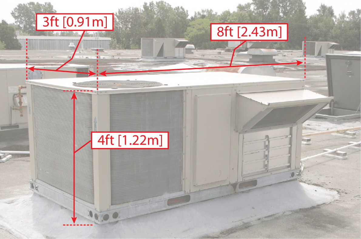
Let’s work through an actual example now to see how this all works. We will consider a HVAC unit on top of a flat roof building. Please note that although we are assuming the roof is flat, the standard just requires that we provide the mean roof height, and so this method would apply to any style of roof. We will use ASCE 7-16 for this example and the building parameters are as follows:
Wind Speed: V = 150 mph [67.1 m/s]
(Based upon Category III)
Exposure: C (Open Terrain)
Topography: Flat, no topographic features
Building Mean Roof Height: h = 50 ft [15.2 m]
Building Length: W = 100 ft [30.48 m]
Building Width: W = 50 ft [15.24 m]
Rooftop Equipment (HVAC) Length: L = 8 ft [2.43 m]
Rooftop Equipment (HVAC) Width: W = 3 ft [0.91 m]
Rooftop Equipment (HVAC) Height: W = 4 ft [1.22 m]
The Rooftop equipment is oriented so that the length of the equipment is aligned with the length of the building.
Calculations:
The all references in the following calculations are per ASCE 7-16.
First we need to calculate the velocity pressure at the mean roof height:
Table 26.11-1 for Exposure C:
zg = 900 ft , Alpha = 9.5
Kh = 2.01*(z/zg)^(2/Alpha) {Table 26.10-1}
Kh = 2.01*(50/900)^(2/9.5) = 1.094
Kzt = 1.0 {Site has no topographic features}
Kd = 0.85 {Table 26.6-1 for Rooftop Equipment}
Ke = 1.0 {Site is near sea level}
qh = 0.00256*Kh*Kzt*Kd*Ke*V^2 {Eqn 26.10-1}
qh = 0.00256*1.094*1.0*0.85*1.0*150^2 = 53.56 psf [2.56 kPa]
Now we need to determine Af, the vertical projected area normal to the wind. Since our equipment is rectangular, we need to calculate this for both orthogonal directions:
Wind Normal to 3 ft Face: Af = 3 ft * 4 ft = 12 sq ft [1.11 sq m]
Wind Normal to 8 ft Face: Af = 8 ft * 4 ft = 32 sq ft [2.97 sq m]
When calculating the horizontal projected area, Ar, the value will be the same regardless of the wind direction:
Ar = 3 ft * 8 ft = 24 sq ft [2.23 sq m]
For the lateral force calculation we now need to determine the GCr, and to do that we need to determine where Af is in relation to 0.1*Bh and Bh. B is the width of the building normal to the wind direction, and so B will be different for each direction we consider.
Wind Normal to 3 ft Equipment Face: h = 50 ft [15.24 m] and B = 50 ft [15.24 m]
Bh = 50*50 = 2500 sq ft [232.3 sq m]
0.1*Bh = 0.1*2500 = 250 sq ft [23.2 sq m]
Since Af = 12 sq ft [1.11] that is well below 0.1*Bh = 250 sq ft [23.2], and so GCr = 1.9
Wind Normal to 8 ft Equipment Face: h = 50 ft [15.24 m] and B = 100 ft [30.48 m]
Bh = 100*50 = 5000 sq ft [464.5 sq m]
0.1*Bh = 0.1*5000 = 500 sq ft [46.5 sq m]
Since Af = 32 sq ft [2.97] that is well below 0.1*Bh = 500 sq ft [46.5], and so GCr = 1.9
For the vertical force calculation, we need to determine GCr, and this is dependent upon Ar. These calculations are also dependent upon B that we used earlier, but it also uses L which is the building dimension in the direction of the wind.
Wind Normal to 3 ft Equipment Face: L = 100 ft [30.48 m] and B = 50 ft [15.24 m]
BL = 100*50 = 5000 sq ft [464.5 sq m]
0.1*BL = 0.1*5000 = 500 sq ft [46.4 sq m]
Since Ar = 24 sq ft [2.23] that is well below 0.1*BL = 500 sq ft [46.4], and so GCr = 1.5
Wind Normal to 8 ft Equipment Face: L = 50 ft [15.24 m] and B = 100 ft [30.48 m]
BL = 50*100 = 5000 sq ft [464.5 sq m]
0.1*BL = 0.1*5000 = 500 sq ft [46.5 sq m]
Since Ar = 24 sq ft [2.23] that is well below 0.1*BL = 500 sq ft [46.5], and so GCr = 1.5
Now we bring together all of these terms to calculate the lateral force (Fh) and vertical uplift force (Fv) on the rooftop equipment:
Wind Normal to 3 ft Equipment Face:
Fh = qh*GCr*Af
Fh = 53.56*1.9*12 = 1221 lbs [5434 N]
Fv = qh*GCr*Ar
Fv = 53.56*1.5*24 = 1928 lbs [8580 N]
Wind Normal to 8 ft Equipment Face:
Fh = qh*GCr*Af
Fh = 53.56*1.9*32 = 3256 lbs [14491 N]
Fv = qh*GCr*Ar
Fv = 53.56*1.5*24 = 1928 lbs [8580 N]
Faster and Easier:
That wasn’t too complicated, but it also wasn’t exactly simple either. There is a faster way to do this using MecaWind software. Lets work through this same example using the MecaWind Software. If you would like to follow along using your own copy of MecaWind, here is a link to download the input file; however, since the inputs are simple it’s just as easy to enter your own model using the screen shots provided here.
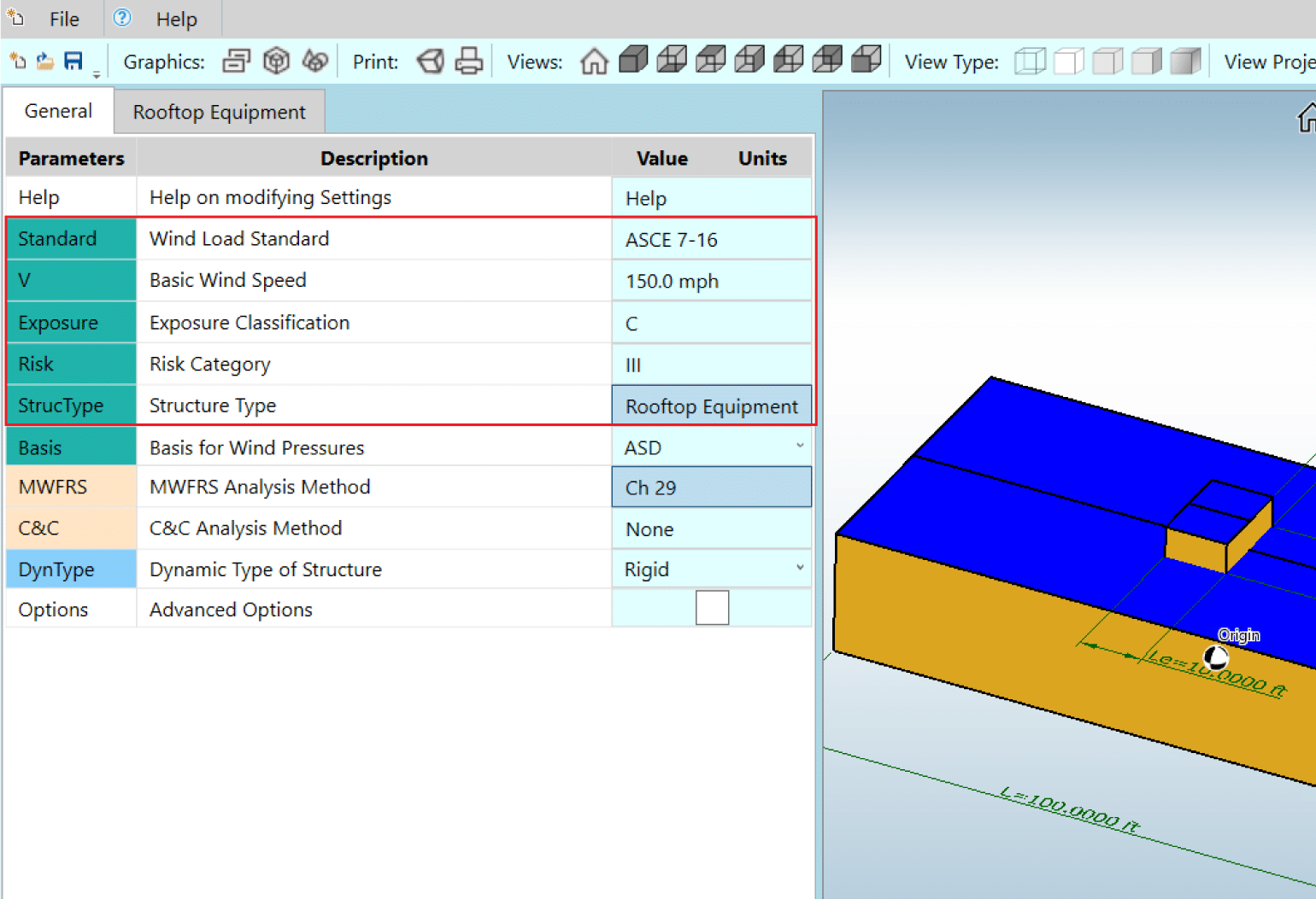
The first step is to enter our wind parameters and select our structure type as “Other” and then select “Rooftop Equipment”. See inputs in corresponding image.
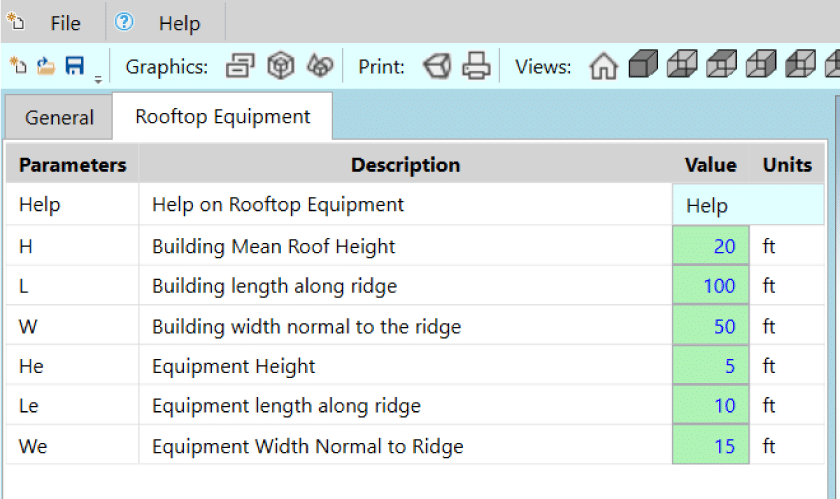
Now we enter the dimensions of our rooftop equipment and building. Please keep in mind that the graphic always assumes a flat roof, but that doesn’t matter since the calculation is purely based upon the mean roof height. Therefore if you had a gabled roof, and the mean roof height of that gable is 50 ft then that is still the value you would enter here. If you are using metric units, there is a toggle to change the units to metric below the graphic.
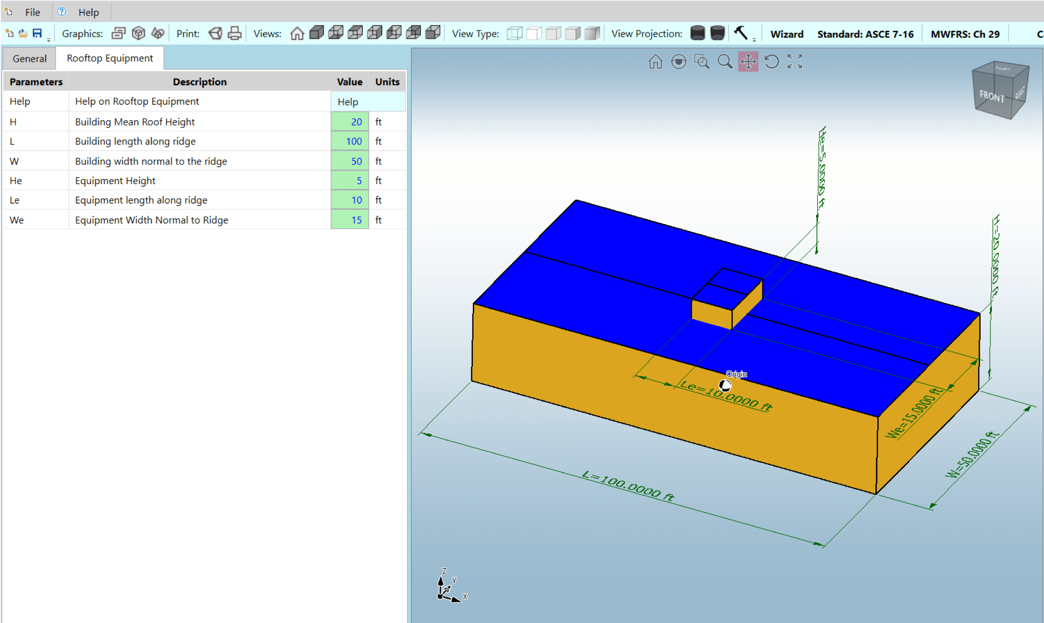
That’s it for the inputs. Now we just click “Perform Analysis” and get our results. The results match very closely to those calculated above, with some minor discrepancies due to round-off error.

Mechanical Equipment Screens:
In the commentary of ASCE 7-16 (Section C29.4.1) there is some discussion about Mechanical Equipment Screens. These are often used to conceal plumbing, electrical, or mechanical equipment from view. They are defined as rooftop structures not covered by a roof and are located away from the edge of the building roof such that they are not considered a parapet. These can be solid or porous panels, the latter of which allows some wind to flow through the panel. The commentary states that little research is available to provide guidance for determining wind loads on these screens as well as the equipment behind the screens. Consequently, ASCE 7-16 recommends that the screens (whether solid or porous) and all of the equipment behind the screens should be designed for the FULL wind load determined in accordance with Section 29.4.1. The only exception to this is when the situation has been appropriately analyzed using the Wind Tunnel Procedure in Chapter 31.
