Getting Twisted about Helical Strakes
Jun 25, 2019

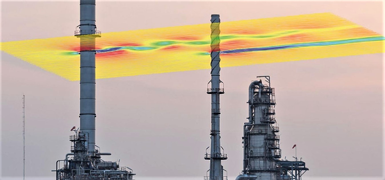
If you have a vortex shedding problem on a stack, then in some cases helical strakes are your best option; however, there are other cases where helical strakes are not the best option.

When not to use Helical Strakes?

If there is another stack (or tall structure) that is nearby, then the interference effects will cause the strakes to become inadequate for stopping vortex shedding. The rule of thumb is that no other tall stacks or structures within about 10 to 15 diameters of the stack. For example, if the stack was 3 m OD, then we need to make sure that we don’t have any other tall structures within 3 m x 15 = 45 m.

The Euro Standard EN 1993-3-2 has some additional criteria for strakes, see ‘Does MecaStack indicate if the strakes will work’ for details. 
What are the Disadvantages of using Strakes?

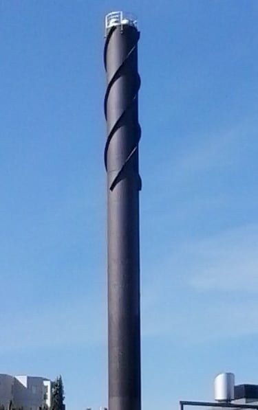
When strakes are added, the drag coefficient of the stack is increased greatly. A smooth cylinder will have a shape factor of 0.7, while the same stack with strakes will increase its shape factor to 1.4. Consequently the load on the top 1/3 of the stack is doubled. Since a stack is like a large cantilever beam, increasing the forces at the top by a factor of 2 will increase the loads at the base by approximately 1.5. Similarly, the deflections will also increase significantly. A general rule of thumb that Meca uses is that helical strakes are often an economic alternative for stacks up to about 100 ft [30 m] tall, and over that it is often more economical to look to a damping solution.

Another disadvantage is that helical strakes can be difficult to fabricate. The tricks in fabricating strakes are not widely known, and so unless you are a company that fabricates strakes regularly, it can be challenging.

Does MecaStack indicate if the strakes will work?

Helical strakes can be added in MecaStack. Go to the “Design”, “Damping” menu, and there is a helical strake option. The button at the right, “Damping Device Menu”, lets you enter the parameters. Although MecaStack does let you simulate helical strakes, their use still requires some engineering judgment. The software will consider the additional along wind loads, by considering the higher shape factor that is entered on this “Damping Device Menu” (default Cf = 1.4). As far as vortex shedding is concerned, the software assumes that you know what you are doing when adding the helical strakes. The software can not determine how well they will work at addressing vortex shedding. This is completely a judgment by the user, because there are no equations or methods to predict how effective they will be in suppressing vibration.

The one exception to this is the Euro Standard EN 1993-3-2.  In Appendix B Section B.2 if the strake criteria is met, then they provide a way to calcualte the reduced the vortex shedding loads on the stack.  The strakes must meet the following:

Check 1: 4.5b <= Strake Pitch <= 5b
Check 2: 0.1b <= Strake Depth <= 0.12b
Check 3: 0.3h <= Strake Length <= 0.5h
Check 4: Unstraked portion at top <= b
Check 5: Scruton Number > 8
where b = Stack Diameter, h = Stack Height

If all this criteria is met then the vortex shedding loads are multiplied by this factor:

Alpha = (1 – Ls / h)^3   , where Ls is the length of stack with strakes

This check from the Euro standard is present in MecaStack v5551 and later. 

Can I use Segmented Strakes?

Segmented strakes are popular because they are much easier to fabricate. Rather than having a continuous helical strake, short segments are placed in a random or helical pattern. These strakes are not recognized by the major stack design standards. We have encountered stacks with segmented strakes that had vibration problems, and so their use is not recommended.

Can I deviate from the Standard?

The standard for fabricating strakes is as follows:

Strake Width = 0.1 * Stack Diameter
Strake Pitch = 5 * Stack Diameter
Three (3) strakes, 120 deg apart
Strake Length = 1/3 of the Stack Height

There are many instances where it is not desireable to meet all of these standards, and here are some common examples:

  • Don’t want strakes on a flare tip
  • There are stiffening rings and so the strake can’t be continuous
  • There is a conical transition in the upper 1/3 of stack
  • Strakes interfere with ladders and platforms

The ASME STS-1 standard provides the following guidance on these issues:

Each strake is to be aerodynamically continuous except at specific locations where cuts may be necessary to clear ring stiffeners or other attachments.”

Based upon this guidance, minor breaks for stiffening rings and other similar attachments should be ok; however, start and stop the strake immediately on each side of the ring. Based upon our experience, strakes are usually not provided on a flare tip, and we are not aware of any issues; however, common sense needs to be applied. If the the upper 1/3 of the stack is 20 ft, and the flare tip is 10 ft, then it doesn’t seem wise to remove 1/2 of the recommended strake length. Conical transitions are a more difficult situation. Vortex shedding is usually limited to one diameter, since the critical wind speed is based upon the diameter. It would seem that it might not be important to strake the conical transition. Our practice is that we try to avoid this situation of having a cone in the upper 1/3 of the stack whenever possible.

The Euro Standard EN 1993-3-2 has some criteria for what is consider acceptable for strake parameters, refer to section ‘Does MecaStack indicate if the strakes will work’ for those details.