
Stack Conical Transition Analysis
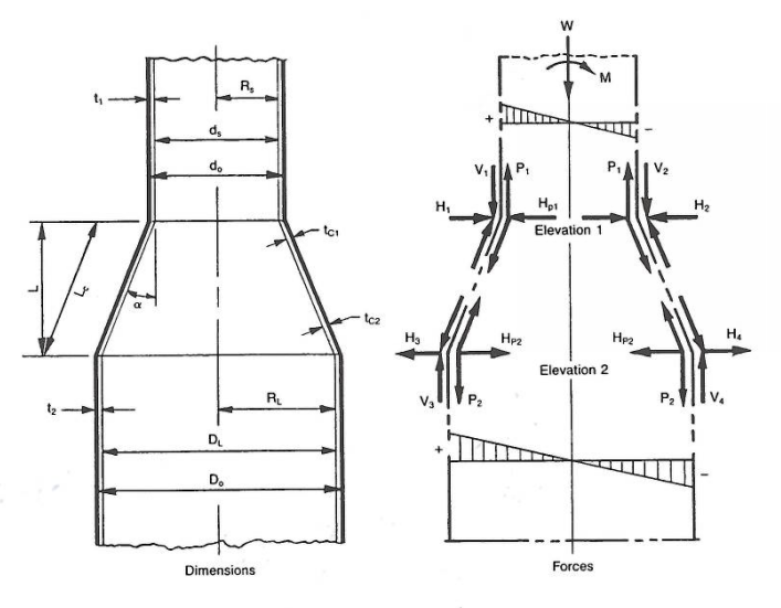
Analysis of a conical transition isn’t as simply as looking at just the section properties along the cone. Cone-cylinder junctions are areas of high discontinuity stresses. They have unbalanced radial loads from the axial and bending loads it sees, as well as localized bending stresses due to the angle change. The standards that most appropriately fit for steel stacks are offshore standards (API RP-2A, NORSOK N-004, ISO 19902) since conical transitions are widely used in offshore structures, particularly offshore wind turbines.
Background
All the offshore standards previously listed reference Boardman’s studies in the 1940s for their origination of their stress formulas. These original papers were concerned with water towers with internal hydrostatic loads, but the commentaries of theses standards don’t show the derivation of their equations based on theses papers. It should be noted that the existing code provisions’ accuracy quickly deteriorates for cases where plate thickness in the cylinder and cone side differ, but they do so on the conservative side and give higher stresses than what would truly be observed. It is also demonstrated that the junction bending and hoop stresses are tied to assumptions of equal cylinder/conical thicknesses and small alpha (α) angles. Even though the standards allow alpha angles up to 30 degs, most cases of unstiffened cone angles are designed to be less than 10 deg and rarely go beyond 15 deg without stiffeners.
Therefore, for cone design, it is recommended, when possible, to keep the cylinder and cone thicknesses the same or close to the same, and to keep α at a maximum of 15 degrees when possible.
MecaStack uses API RP 2A-WSD for its cone analysis in a steel stack structure, and this will be the standard that will be used in the discussion of this article.
Conical Transitions
The analysis should involve a check on the: cone section properties, cylinder/cone local buckling, cylinder/cone local bending stress caused by longitudinal stresses (global axial and bending), and hoop stress at the junction.
To help with clarity, an example cone will be defined to better illustrate the analysis, and the top junction will be analyzed.
The stack will be 100ft tall, 1/4″ thick, A36 at 300 deg F, and the cone will be at mid height.


Cone Section Properties:
The cone section properties check is handled within MecaStack. The program already breaks the entire stack into short elements for calculating the properties for stress calculations, so the cone section properties is included in this process when a cone is present. Thus, this item won’t be discussed in this article, besides what the API RP 2A standard states about it.
The standard states: “The nominal axial and bending stresses at any section in a cone transitionare given approximately by (fa + fb)/cos(α), where alpha equal one-half the projected apex angle of the cone (see post image for the half apex angle example) and fa and fb are the nominal axial and bending stresses computed using the section properties of an equivalent cylinder with diameter and thickness equal to the cone diameter and thickness at the section.”
Local Buckling:
Checked for top and bottom junction.
Local buckling is checked for the compression case of the conical transition analysis. The API standard says that with an α less than 30 degress that equivalent cylinders with diameters equal to D/cos(α) may be used, where D is the cone diameter at the point under consideration. The NORSOK standard adds on to say that cones with a constant thickness (recommended), using the diameter at the large end of the cone would be conservative. The diameter is used to calculate the inelastic local buckling stress, Fxc, which will be the limit for the compression case of fa + fb.
To calculate Fxc, we first need to calculate the elastic local buckling stress, Fxe. API and NORSOK both give the equation for Fxe as: Fxe = 0.6*E*tt/D
Fxc is then determined by two equations depending on D/t.
- If D/t <= 60, then Fxc = Fy
- If D/t > 60, then Fxc = Fy[1.64-0.23*(D/tt)^(1/4)] but must be less than or equal to Fxe
In our top junction example case, our D/tt = 192 so we would use equation 2, which results in our Fxc as 24.926 ksi. This values is compared against fa + fb, which in our case is 5.109 ksi. This gives us a stress ratio of 0.205, which is less than unity meaning we pass this stress check.
Longitudinal Stress
Checked for top and bottom junction on cone side and top and bottom junction on cylinder side.
The localized bending stress at an unstiffened cone-cylinder junction of a conical transition may be estimated from the following API standard equation, which were based on results presented in the Boardman papers:
fb’ = (0.6tt*(D(tt+tc))^(1/2) / te²)*(fa + fb)*tan(α)
where te is the thickness in the cylinder section or cone section depending on which side of the junction is being investigated.
In this case both our cylinder and cone thicknesses are the same so we will receive the small results for fb’ which is found to be: 15.017 ksi.
As a comparison, the NORSOK equation is 0.85(D/tt)^(1/2) *(fa + fb)*tan(α) and has been shown to give more accurate results on the cylinder side but less accurate results on the cone side.
For strength requirements, the total stress of fa + fb + fb’ should be limited to the minimum tensile strength, Fu, of the cone and cylinder material, and our axial stress of fa + fb should be limited to the appropriate allowable stress, which would be tension since we already checked our compression case of fa + fb and the allowable tension stress is defined as 0.6Fy in the API code.
Thus, our total stress would be 5.109 + 15.017 = 20.126 ksi, and would be compared against 58.0 ksi to give a stress ratio of 0.347, which is less than 1.0 meaning we pass the total stress check.
For our tensile stress, this would actually be –fa + fb since our axial load will alway be in compression. The tensile stress is thus 4.791 ksi and compared against 19.08 ksi (0.6*31.8), resulting in a stress ratio of 0.251 and passing the stress check.
Hoop Stress:
Checked for top and bottom junction.
The hoop stress is caused by the unbalanced radial line load and may be estimated by:
fh’ = 0.45(D/tt)^(1/2) *(fa + fb)*tan(α)
As a comparison, NORSOK gives the same equation for hoop stress.
NORSOK gives further instruction on this equation stating that at the smaller-diameter junction, the hoop stress is tensile (or compressive) when fa + fb on the cylinder side is tensile (or compressive). Contrastly, the hoop stress at the larger-diameter junction is tensile (or compressive) when fa + fb on the cylinder side is compressive (or tensile).
We are looking at the top junction (smaller-diameter junction) of our conical transition so our hoop stresses will be:
- Tension, fht’ = 0.45*(48/0.25)^(1/2) * (-0.159 + 4.950) * tan(14.036 deg) = 7.469 ksi
- Compression, fhc’ = 0.45*(48/0.25)^(1/2) * (0.159 + 4.950) * tan(14.036 deg) = 7.964 ksi
For hoop tension, fht’ should be limited to 0.6Fy, which gives us a stress ratio of 0.391 and passes the stress check. For hoop compression, fhc’ should be limited to 0.5Fhc, where Fhc is computed from the following equations using Fhe as 0.4*E*tt/D:
- When Fhe <= 0.55Fy, Fhc = Fhe
- When 0.55Fy < Fhe <= 1.6Fy, Fhc = 0.45Fy + 0.18Fhe
- When 1.6Fy < Fhe <= 6.2Fy, Fhc = 1.31Fy / 1.15+(Fy/Fhe)
- When Fhe > 6.2Fy, Fhc = Fy
In our example case we would use equation 3 because Fhe = 58.96 and that fits between 1.6Fy (50.88) and 6.2Fy (197.16), and using this equation gives us Fhc as 24.66 ksi. Our fhc’ (7.964 ksi) is compared to 0.5Fhc (12.329 ksi) and gives us a stress ratio of 0.646 and passes the stress check.
Cone-Cylinder Junction Rings
If any of the stress checks for the conical transition we went through fail, then stiffening rings are required and the section properties of the ring should be chosen to satisfy both the following requirements (NORSOK and API are in agreement with these requirements):
- Cross-Sectional Area of Composite Ring Section: Ac = tt*D/Fy *(fa + fb)*tan(α)
- Moment of Inertia of Composite Ring Section: Ic = tt*D*Dc²/8E *(fa + fb)*tan(α)
where Dc is the diamter to the centroid of the composite ring section.
In computing Ac and Ic, the effective width of shell wall acting as a flange for the composite ring section may be computed as: be = 0.55((D*tt)^(1/2) + (D*tc)^(1/2))
Conclusion
When a conical transition is designed for a steel stack, the following items need to be analyzed:
- Cone section properties at each end of the cone
- Local buckling at each end of the cone
- Yielding and local bending on the cone and cylinder side and at each end of the cone
- Hoop stress at each of the cone
As with most standards, the stresses obtained from their equations will give more conservative stresses than what are actually observed. The differing of standards for conical transitions lead to research to compare the formulated stresses with the actual stresses and analyzed the findings.
For junction local bending on the cylinder side API and NORSOK the same stresses when the cylinder and cone thicknesses are the same. As the thicknesses differ API will give more conservative values.
For junction hoop stress on either side API and NORSOK use the same equation and thus give the same results.
For junction axial stress on the concial side the three standards all give roughly the same results.
For junction bending stress on the conical side the three standards give the same stresses when the cylinder and cone thicknesses are the same. As the thicknesses differ NORSOK (ISO 19902:2020 uses same equation) significantly overestimates the stresses, where as API (ISO 19902:2007 uses same equation) gives more realistic stresses but still on the conservative side.
MecaStack uses the API RP-2A-WSD standard for its conical transition analysis in stack design and from the research that has been done. We believe this to currently be the best option available when analyzing a cone for our purposes, short of a finite element analysis.