
Wind Loads on Freestanding Walls

This article addresses the method used to calculate wind loads on a freestanding wall. This calculation follows the same method as that used for solid signs, which we have covered in a previous article. The calculation of wind loads on freestanding walls is most commonly applied towards fences. This article describes the method followed for the calculation of wind loads on free standing walls.
Wind Load Formula:
Wind loads on Signs and Freestanding walls is covered in ASCE 7-16 by Section 29.3 “Design Wind Loads: Solid Freestanding Walls and Solid Signs”. The formula is very simple and one we have seen many times in ASCE 7-16, with the only exception being the introduction of the Cf, which is a net force coefficient taken from Figure 29.3-1.
This method applies to a “solid” sign. A sign or freestanding wall is considered to be solid if the openings comprise less than 30% of the gross area of the sign or freestanding wall. Forces on solid signs with openings shall be permitted to be multipled by the following reduction factor:
Reduction Factor = 1 – (1-e)^1.5
e = Solidity Ratio = Solid Area / Gross Area

ASCE 7-16 Figure 29.3-1 Force Coefficients Cf
The biggest task in calculating wind loads on freestanding walls is to determine the force coefficient from Figure 29.3-1. In this figure there are up to three different loading conditions that may need to be considered, Case A, B, and possibly C.

In figure 29.3-1 it states that Case A and B must be considered for all S/h < 1, which basically covers the range of nearly all possiblities. Case C must only be considered when B/s>= 2, which means it must only be considered if the sign width is at least double its height.
Wind Load on Freestanding Wall (Fence) Example:
Let’s work an example to illustrate this method. We have a wall that is 6 ft [1.829 m] high by 120 ft [36.58 m] long. For the example, we will consider it a single free standing fence without any 90 degree returns on either end.
ASCE 7-16, 120 mph, Exp. C, Category II
Mean Structure Height (h) = 6 ft
Table 26.11-1 for Exp C –> zmin = 15 ft, zg = 900 ft, Alpha = 9.5
z = 6 ft (Mean roof height)
Kh=2.01*(6 ft / 900 ft)^(2/9.5) = 0.849
Kzt = 1.0 (No topographic feature)
Kd = 0.85 (per Table 26.6-1)
Ke = 1 (Sea Level)
Calculate Pressure at Mean Roof Height:
qh = 0.00256*Kh*Kzt*Kd*Ke*V^2
= 0.00256*0.849*1*0.85*1*120^2 = 26.6 psf [1.273 KPa]
B = 120 ft [36.576 m]
s = 6 ft [1.829 m]
h = 6 ft [1.829 m]
B/s = 120 ft / 6 ft = 20
s/h = 6 ft / 6 ft = 1.0
Case A Wind Loads:
Referring to Figure 29.3-1 for B/s = 20 and s/h = 1 we get a Force coeffient of 1.3

Case A force becomes:
Fa = qh * G * Cf * As = 26.6*0.85*1.3*(6*120) = 21,162 lbs [94.18 KN]
Case B Wind Loads:
Case B wind loads are identical to Case A, except that they are applied at an offset from the center of the face (see diagram). Since the sign is not double-faced, we don’t have the special conditions indicatedin Fig 29.3-1, Note 3. That means the eccentricity for the sign becomes:
Dx = 0.2*B = 0.2*120 ft = 24 ft [6.096 m]
Fb = Fz = 21,162 lbs [94.18 KN]

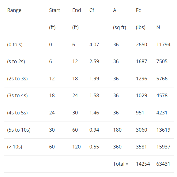
Case C Wind Loads:
Since B/s = 20 which is >= 2, we must consider Case C. We refer again to Figure 29.3-1 and obtain the force coefficients for the case C.

From the table we determine the following Force Coefficients:
Cf (0 to s) = 4.07 (0 to 6 ft)
Cf (s to 2s) = 2.59 (6 ft to 12 ft)
Cf (2s to 3s) = 1.99 (12 ft to 18 ft)
Cf (3s to 4s) = 1.58 (18 ft to 24 ft)
Cf (4s to 5s) = 1.46 (24 ft to 30 ft)
Cf (5s to 10s) = 0.94 (30 ft to 60 ft)
Cf (>10s) = 0.55 (>60 ft)
With these values we can then calculate the forces:
qh*G*As = 26.6*0.85*6*120 = 16,279 lb
The forces are applied at the center of each of the spans.

Same Example Using MecaWind
Now we perform the same set of calculations using the MecaWind software. The input file can be obtained here, and the output file here. The output results match exactly those which we have calculated here.
