The Next Big Thing in Lifting Lug Design
All structural design is important but verifying that the lifting lug design is adequate to lift a piece of heavy equipment might just be one of the most important things an Engineer can design. Engineers often design structures and equipment for extreme wind, seismic and other loading that may never occur; however, in the case of a lifting lug those extreme loads may very well be experienced at the beginning of the equipment life cycle, not 20+ years down the road. The failure of a lifting lug could very likely put human life in danger, in the event of a failure. Imagine being on-site during an important lift, you want the peace of mind to know that those lifting lugs were designed to DEFINITELY lift the equipment safely. Meca Enterprises has developed the program, MecaLug, to easily design lifting lugs and lifting systems to give that peace of mind.
Design Standard
The design standard followed for the the lifting lug designs is ASME BTH-1 “Design of Below-The-Hook Lifting Devices.” This is a widely used design standard for designing lifting devices and provides a solid reference that the designer can use with confidence to produce a safe design.
Lifting Lug Overview (Standard & Pro Version)
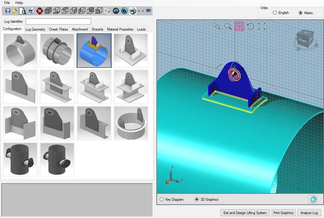
Both versions of MecaLug allow the user to design a single lifting lug from a variety of configurations that are most commonly used in the industry. Understandably, there are countless other lifting lug configurations that can be used by companies and it’s not feasible to include every possibility. Once the configuration is chosen, the user will see a graphical representation of the lug configuration that will dynamically update when lug parameters are updated.
Once all the attributes for the lug model have been entered, the last entry needed for the analysis is the estimated loads the lug will see during the lifting operation. MecaLug will then run the analysis on the lifting lug design and the element the lug is attached to, to ensure the design is adequate for use.
Lifting System (Pro Version Only)
What do you do if you don’t know the loads the lug will see during the lifting operation? That’s where the Pro version of MecaLug comes in.
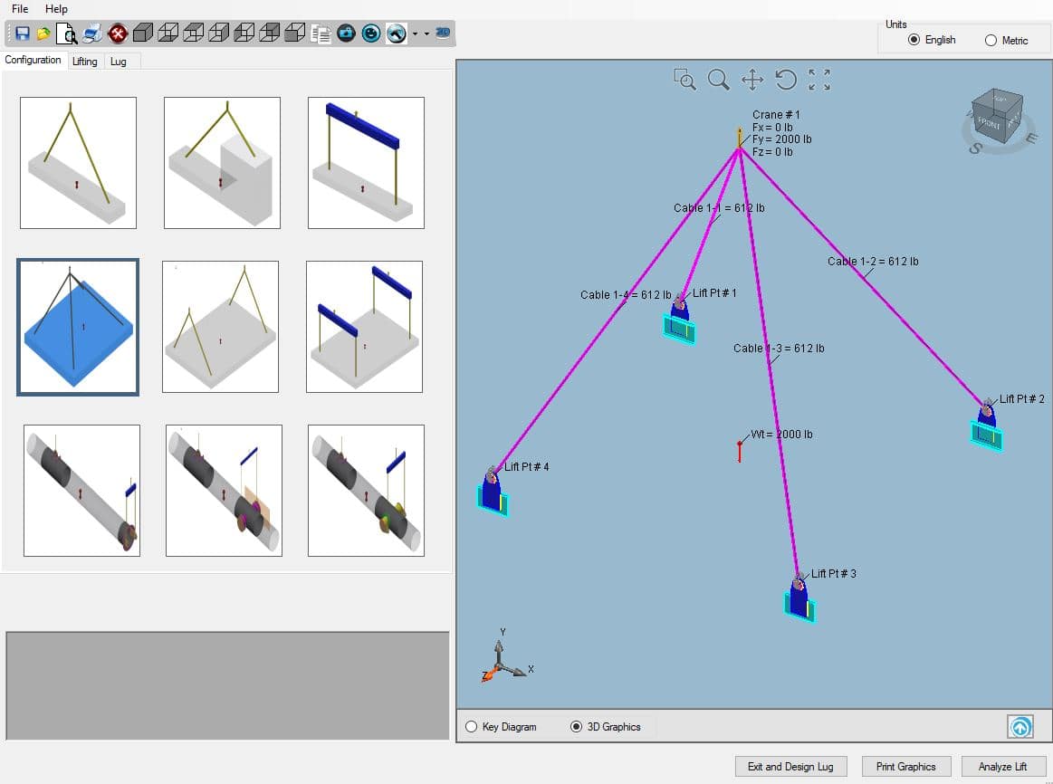
A lifting system is comprised of 2 or more lifting points, and finding the loads acting on each lifting point can be challenging. MecaLug Pro allows the user to pick one of several standard lifting system designs, and then simply enter the dimensions that match your design. The user can select which lifting lug is to be used for each lifting point and has the ability to rotate the lug about all 3 axes. The software also has an option to select “None” for the lifting lugs, if the user only wants to calculate the loads in each cable and the reaction(s) at the crane point(s).
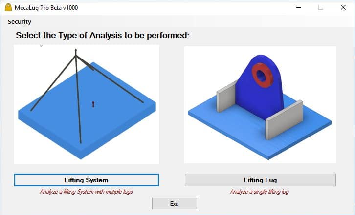
For lifting systems where the lifting cables come up to a single point (as shown below), the geometry of the system can be a little complicated. MecaLug takes the geometry into account and calculates the loads acting on each cable. In addition, the lug is experiencing loads in all three directions (X/Y/Z) and it is analyzed for all of those load components to check the overall integrity of the system.
Stack/Vessel Lifting
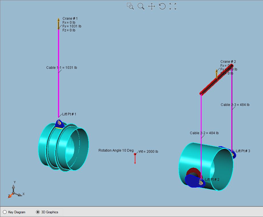
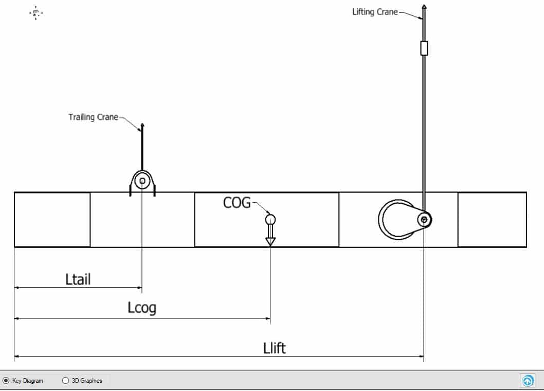
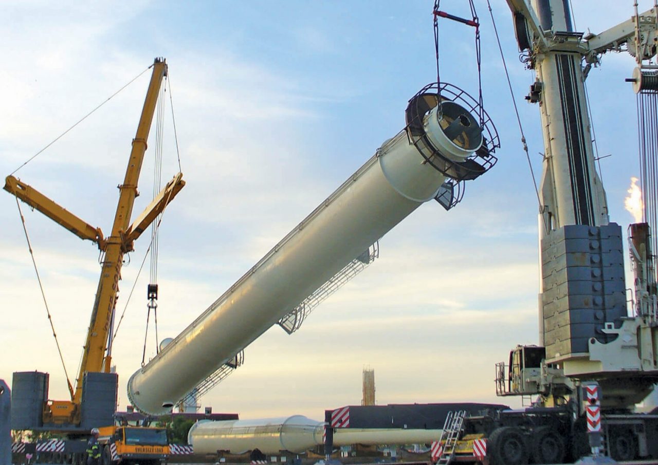
There are unique problems that occur when a stack, vessel, or tower is lifted. The structure usually starts in the horizontal position and then they are rotated 90 degrees to the vertical position. MecaLug analyzes the structure at each increment of the lift and calculates the loads acting on the lifting lugs, trunnions, or tailing lugs at each of these increments.
The output of the analysis summarizes the loads at each lifting angle and checks all lifting lug stresses at each angle so that the worst case can be found. This allows the designer to quickly determine which angle is most severe for the lifting, and design accordingly.
What about Local Stress?
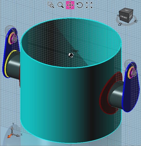
Finite Element Analysis Alternative:
