Too Close for Comfort

How close can you space stacks? It’s a common question, and one that doesn’t have a simple answer. There are several factors that should be considered, and I’m going to go over those factors in this article.
The Theory:
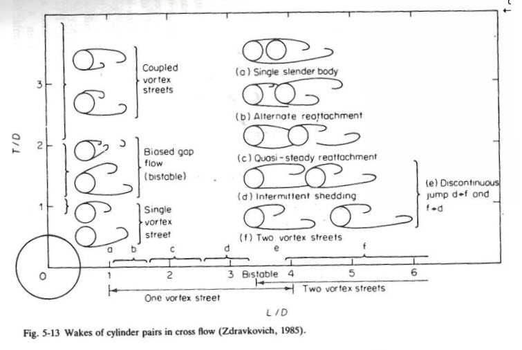
When two cylinders are closely spaced and the wind is approximately acting along a line between the two cylinders, the wake from the upwind cylinder can “interfere” with the flow patterns on the downwind cylinder. Depending upon the spacing, one of several conditions can occur. The chart below is taken from “Flow Induced Vibration” by Robert D. Blevins. Referring to the right side of the figure for tandem cylinders, where the flow is in line with the cylinders, the diameter is ‘D’ and the center to center spacing of the cylinders is “L”. At close spacing (L/D < 1.4) there is only a single vortex street (scenario ‘a’). For L/D spacing between 1.4 and 4 there is very little vortex shedding behind the upwind cylinder (scenarios b, c and d). For spacing 4 and greater there are two distinct vortex streets (scenario f).

The above figure also shows the flow for cylinders that are side by side on the left side of the figure. In the side by side scenario, T is the center to center spacing of the cyilinders. From the figure we see that at spacings below 4 diameters, the cyilnder flow patterns are interacting with each other, and above 4 they are basically independent.
According to Blevins (see reference above), there are three mechanisms for flow-induced vibration of pairs of cylinders in cross flow:
1) Vortex-induced vibration when spacing exceeds 1.4 diameters.
2) A fluid elastic instability of the general type observed in tube arrays for spacing between 1.1 and 8 diameters (this seems to be more applicable to tube arrays).
3) Wake galloping when the cyilinders are spaced greater than 8 diameters and the downstresm cylinder falls in the wake of upstream cylinder (this appears to be more related to cables and power lines).
Meca’s interpretation of the above is the # 1 (vortex-Induced vibration) is the most relevant to steel stacks and chimneys.
What do the Design Standards recommend:
There are several design standards for steel stacks, and it is useful to compare some of the more comprehensive standards for stacks and see what each recommends with regard to interference effects.
ASME STS-1-2016:
When the spacing is less than 15 diameters, then the Strouhal Number shall be determined from eq. 5-8
A/D <= 15: S = 0.16 + (1/300)*(A/D – 3)
A/D > 15: S = 0.2
A = Center to center spacing of stacks
D = Diameter of stacks at top
For all stacks that have a spacing less than 3 diameters then you have to do a wind tunnel test or rely on some proven tests.
CICIND 2010:
When spacing is less than 15 diameters, then wake interference effects can be significant.
Helical strakes are ineffective when there are interference effects and shouldn’t be use. (Meca has found this to be true, don’t use helical strakes for closely spaced stacks, D < 15)
The magnitude of estimated deflection due to vortex shedding is increased by a factor that is dependent upon the spacing and applies when spacing is between 10 and 15 diameters.
If the spacing is less than 10 diameters then they recommend the use of a Tuned Mass Damper (TMD).
The strouhal number must be reduced when the spacing is between 10 and 15 diameters per Fig 7.6.
There is a formula for an increase factor on the wind velocity that varies betwen 1 and 1.2 depending upon the spacing. The standard recommends higher wind speeds be considered when the spacing is closer, due to higher wind drag on the downwind structure.
European Standard EN 1991-1-4:2005:
The standard recommends that the magnitude of the deflection due to vortex shedding is increased by 1.5 when the spacing is between 1 and 10 diameters.
The Strouhal number is to be reduced per Eqn E.11:
1 <= A/D <= 9: S = 0.1 + 0.085*log(a/b)
A/D > 9: S = 0.18
A = Center to center spacing of stacks
D = Diameter of stacks at top
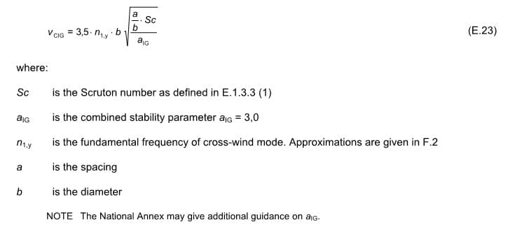
If the spacing is less than 3 diameters then an equation is provided to estimate the new critical wind speed. (Eqn E.23)

Does MecaStack do all of this?
MecaStack will adjust the Strouhal number if you specify the stack as a “Group” and enter the spacing. The Strouhal number will be adjusted based upon the design code criteria selected (If applicable). At the time of this writing the strouhal number will be adjusted for the spacing; however, it doesn’t also run the case where the wind is not in line. Therefore we recommend you make two runs, one with the group setting and another with the stack as an isolated stack, and determine which is worst.
Regarding the special criteria in CICIND for the increase in along wind loads, at the time of this writing this feature was not included in MecaStack.
Conclusion:
This is a complicated topic and as can be seen in the different codes there are some variations on how they each handle this issue. We recommend the following approach:
1) Do Not Use Helical strakes when center to denter spacing of stacks is less than 15 Diameters.
2) In MecaStack, make two analysis runs. One with the grouped stack specified, and another without. Use the one that gives the highest estimated deflection due to vortex shedding.
3) Try to avoid the case where the spacing is less than 4 diameters, or consult an expert.
4) Consider increasing the along wind loads (Per CICIND 2010) when you have closely spaced stacks. This is conservative, since the increase occurs only when wind is acting along the line between the stacks.
