
Life is a Breach

Updated April 16, 2020:
The method of breach analysis discussed in this article is referred to as the “Section Property” method in MecaStack. As of v5506 there is now a method available called the “Troitsky” method, and an article discussing that method is in another article, click here to view the Troitsky article.
A breach is an opening in the cylindrical shell of the stack that compromises its structural integrity. This is usually either a rectangular ducting connection or a cylindrical pipe nozzle penetrating the stack shell.
Selecting the Section Property Analysis:
You may select the section property option for each individual breach, but selecting the option shown to the right on the Breach Reinforcement screen.

How does MecaStack handle Breach Analysis?
MecaStack allows the user to enter either a rectangular breach or a cylindrical nozzle. Both work similarly in that they remove material from the stack shell, but one is rectangular and the other is round. Also, the reinforcement for a rectangular is typically considered as a “stiffener” and for a round nozzle it is a “repad”.

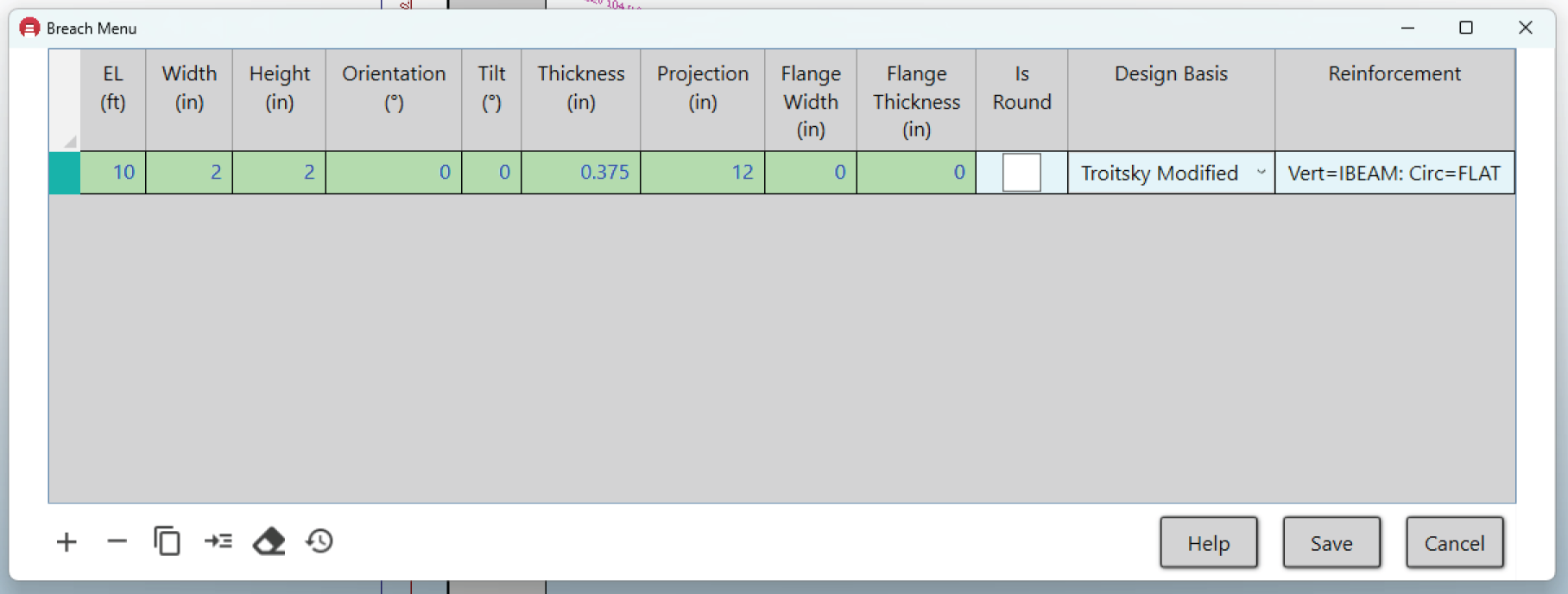
Rectangular Breach:

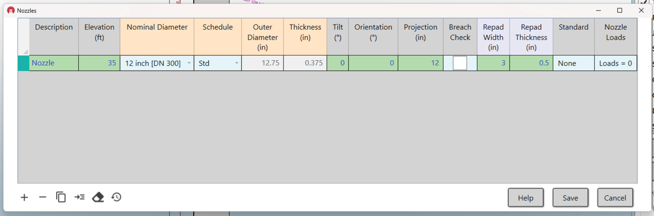
Round Nozzle:
A typical round nozzle (pipe) entry is shown below. The elevation is at the elevation of the intersection between the nozzle and stack shell. The repad width and thickness are entered if there is a reinforcement pad on the nozzle. For example, in the entry below there was a 3″ wide repad that was 0.5″ thick. This is a saddle type reinforcement pad such as those found in pressure vessels.
What is MecaStack doing with this information?
We have entered a rectangular breach and a round nozzle, and with this information MecaStack will calculate reduced section properties. We can visually see this by going to “Analysis” > “Shell Section Properties”. This brings up the screen below, and then you enter the elevation of concern. In this case we enter 10 ft. On the left side of the form it graphically shows the stack with the breach and nozzle represented as removed areas. The repad is shown as it was modeled (3″ wide x 0.5″ thick). The stiffener area on the breach is just represented as a lump of material with the same cross section as what was entered by the user (2 sq in in this example). On the right side of the display is a tabulation of the section properties. At the bottom of the tabulation is the “Ideal Cylinder Only Properties”, which represents the stack cylinder without any consideration for Breach, Nozzles, Repads or Stiffeners. The actual cross section is then calculated numerically, by breaking up the entire cross section into small rectangles. The ratio of “Actual/Ideal” compares the actual properties over the ideal (perfect cylinder). This is provided to give some indication of the reduction in strength of the section. For example, in the output below you can see that the cross sectional area is 89.5% of a perfect cylinder while the moment of inertia is 84.3% of the perfect cylinder.
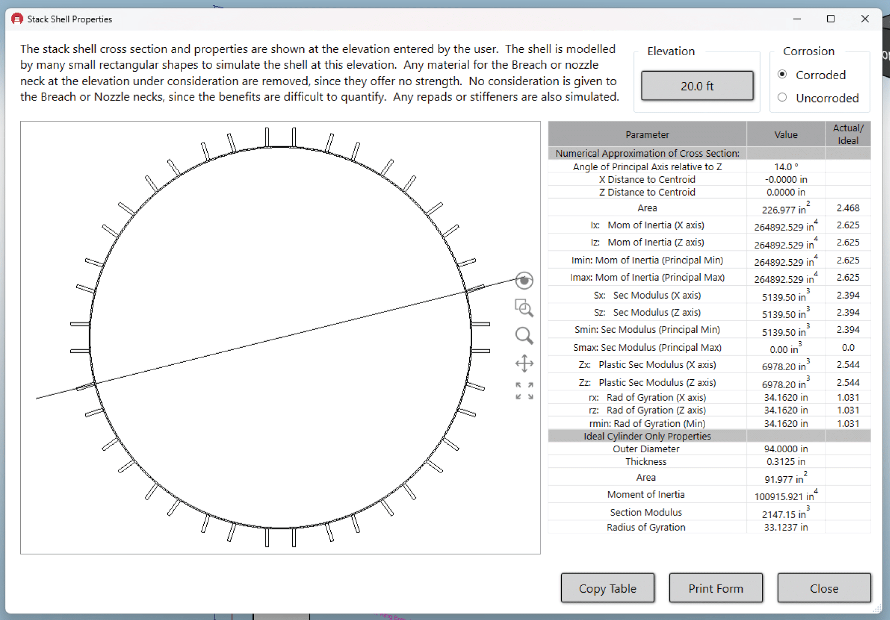
Below shows how the cross section is approximated by breaking it up into small rectangles, and then the properties are calculated numerically.


When can I rely on only MecaStack?

Is it Breach or Breech?
This is a question that has puzzled stack designers since the beginning of time, is it Breach or Breech? Lets look at the definition for each according to Dictionary.com:
Breech – The lower, rear part of the trunk of the body. In an ordnance, the rear part of the bore of a gun, especially the opening and associated mechanism that permits insertion of a projectile.
Breach – The act or result of breaking; break or rupture. A gap made in a wall or fortification. To make a breach or opening in.
According to the definitions, it seems that BREACH is the most accurate for the context of an opening in a cylindrical shell; however, I have been using breech to describe this situation for my entire career. The book “Tubular Steel Structures” by Troitsky uses the term breech, and ASME STS-1 uses breech. Consulting with colleagues they have stated that they believe that the industry has used breech and breach interchangeably, so that either is acceptable.
At the end of the day, we at Meca have decided that breach is more consistent with the definitions and so moving forward we will use breach; however, don’t be surprised if you see breech in various locations in our website and software, it’s going to take a while to locate and update all references.